Strobe Light Installation and Commissioning
This section describes how to commission the strobe light from two aspects: physical cable connection and illumination angle. The strobe light should be commissioned at night.
Installing a Strobe Light
- Determine the installation position.
The strobe light is installed at the same location as the camera. The strobe light should be at least 2 m away from the camera. This prevents light emitted by the strobe lights from affecting camera imaging.
- Determine the illumination direction.
The illumination direction can either be straight or oblique. Straight illumination is recommended for the strobe light.
- Determine the illumination angle.
The illumination angle is determined based on the light spot position. For the strobe light, it is recommended that the light spot be located at the rear of the vehicle in the capture position to ensure that the license plate is not overexposed.
You can observe the image to check the light compensation effect. If the license plate is overexposed, adjust the illumination angle of the illuminator to move the light spot further backwards. If the license plate brightness is insufficient, adjust the illumination angle of the illuminator to properly move the light spot forwards.
- Connect the strobe light to the camera.
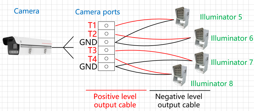
After the camera is installed, connect the strobe light to the camera and power supply. The strobe light can connect to the TTL ports (ports T1 to T4, corresponding to ports T1 to T4 in the camera web system) of the camera. The following describes the cable connection:
The positive level output cable of an illuminator is connected to the TTL port of the camera. The negative level output cable or ground cable (If multiple illuminators are connected, multiple negative level output cables or ground cables need to be connected in parallel first.) to the GND port of the camera, as shown in Figure 3-22.
- If the signal control cable of the illuminator is not clearly identified as a level output or an I/O cable, check the illuminator instructions or consult the illuminator supplier to confirm the signal control cable type.
- The TTL port of ITS cameras can identify only the level ranging from 0 V to 5 V.
Checking Physical Cable Connections
Check whether the strobe light flashes in the video image. If so, the strobe light is not synchronized with the camera.
The detailed procedure is as follows:
- Log in to the camera web system and view the live video image.
- Check whether the strobe light flashes (on and off alternately) in the video image. If so, the physical cable connection is abnormal. Then, go to the next step. If not, the physical cable connection is normal. Then, no further action is required.
- Correct the cable connection. After the cable connection is corrected, you are advised to perform the check again.
Adjusting the Illumination Angle
Check the illumination and light spot position in the detection scene to determine whether the illumination angle is correct. It is recommended that the light spot be located at the rear of vehicles in the capture position.
The detailed procedure is as follows:
- Log in to the camera web system and view the live video image.
- Check the position of the strobe light spot in the video image and the brightness of the vehicle and license plate in the captured image.
If the light spot position is incorrect or the brightness is insufficient, adjust the illumination angle or brightness of the strobe light. The illumination angle is subject to the light spot position. For details about how to adjust the brightness, see the strobe light instructions.

When adjusting the angle of the strobe light, consider the effect of license plates in the scene. If the license plate is overexposed, properly correct the angle of the strobe light until the optimal angle is reached.