Appendix
Logging In to the LDU
Application Limitations
The LDU output resolution can only be 1920 x 1080 pixels.
Procedure
- Power on the device.
- Log in to the LDU, as shown in Figure 3-123.

When you log in to the LDU for the first time, the startup wizard page is displayed. Configure the system following the startup wizard. For details, see Configuring the Startup Wizard.

Verification
After logging in to the LDU, verify that the Live page is displayed by default, as shown in Figure 3-124.

The LDU provides four user roles. Different roles have different operation permissions after logging in to the LDU. Table 3-87 describes the role permissions.
Role |
Permission |
|---|---|
admin |
Supports all LDU operations. |
Live video operator |
Supports live video viewing, gesture password change, logout, restart, and switchover between the primary and secondary screens. |
Recording operator |
Supports live video viewing, recording playback, gesture password change, logout, restart, and switchover between the primary and secondary screens. |
Recording administrator |
Supports live video viewing, recording playback and download, gesture password change, logout, restart, and switchover between the primary and secondary screens. |
If DST is enabled for the device, the DST identifier is displayed on the LDU home page after login.
Changing the Gesture Password
After logging in to the LDU, the live video operator, recording operator, and recording administrator can change the gesture password on the live video viewing page.
- Log in to the LDU.
- Go to the live video viewing page, click
 in the upper right corner, and choose Change Gesture Password.
 - In the Authority Confirm dialog box that is displayed, enter the password, as shown in Figure 3-125.
- Set a new gesture password, as shown in Figure 3-126.


Logging In to the OMU portal
Application Limitations
- Browser: Google Chrome 7.0.276 or later
- Operating system: 32-bit or 64-bit Windows 7/10/11
Procedure
- Check the network connection between the HWT-IVS1800 and computer used for logging in to the OMU portal.
- If the network parameters of the device have been modified, ensure that the computer used for logging in to the OMU portal is properly connected to the network of the HWT-IVS1800.
- If the device is just delivered or has been restored to factory settings, ensure that the computer used for logging in to the OMU portal is directly connected to the HWT-IVS1800 and is in the same network segment (192.168.3.111/24) as the HWT-IVS1800.For a device that is just delivered or has just been restored to factory settings, it works in single-address mode, and its network information is as follows:
- IP address: 192.168.3.111
- Subnet mask: 255.255.255.0
- Gateway address: 192.168.3.1
- Open Google Chrome and set browser parameters.
- Enter chrome://flags/ in the address box of Google Chrome, and press Enter.
- Enter TLS in the search box and check whether TLS 1.2 or TLS 1.3 is enabled. If not, enable it.
- Disable the proxy server.
- Press Alt+F or click
 in the upper right corner of the browser and choose Settings > Advanced > System > Open your computer's proxy settings.
 - Toggle off Use a proxy server in the Manual proxy setup area.
- Press Alt+F or click
- Enter https://IP address:8443 in the address box, and press Enter.
In the preceding URL, IP address indicates the IP address of the .
When two network adapters are enabled for the HWT-IVS1800, the IP address of the GE2 network port (northbound connection) is 10.10.10.10, and the IP address of the GE1 network port (southbound connection) is 192.168.3.111. If the IP address of the computer can communicate with the IP addresses of the two network ports, you can enter https://192.168.3.111:8443 or https://10.10.10.10:8443 in the address box of the browser to log in to the HWT-IVS1800.
- Set the passwords of the service system and operating system accounts upon the first login, as shown in Figure 3-127.
- The password is applied to the admin user of the service system, and the admin and root users of the operating system.
- For security purposes, you are advised to use a password with high complexity. For details about the password complexity requirements, see Suggestions on Password Maintenance.
Table 3-88 describes the parameters of the admin user of the service system, and the admin and root users of the operating system.Table 3-88 Parameter descriptionParameter
Application Scenario
Application Description
Service system
User Name: admin
- The admin user is a service system user and can log in to the OMU portal, LDU, and iClient S100.
- Only the admin user can log in to the LDU
The admin user is a predefined user with full permissions on the system. The permissions and name of the user are specified by default and unconfigurable.
Password/Confirm Password
Operating system
User Name: admin
The admin user, an operating system user, can remotely and locally log in to the operating system and perform operations on some files, directories, or processes.
The password of the admin user needs to be changed upon the first login.
For details about how to change the password, see How Do I Log In to the Operating System Through a Network Port?.
Password/Confirm Password
User Name: root
The root user has all the permissions on the operating system and can perform operations on any file, directory, and process.
You must log in the operating system as the admin user first and then switch to the root user.
Password/Confirm Password
- Use the configured service system password to log in to the OMU portal again.
- Set the password protection mode upon the first login to the OMU portal, as shown in Figure 3-128.Figure 3-128 Configuring password protection upon the first login

- Click Skip to skip the current page for configuring password protection and perform operations described in How Do I Change the Security Questions?.
- Select a password protection method and set related parameters.
- Select the check box next to Security question and set security questions and answers.
- You can select preset questions or customize questions. A customized question must contain 1 to 80 bytes and cannot contain the following special characters: ~ ` ! ^ = { } | \ [ ] < > '
- For customized questions, their answers (excluding the space at the beginning) must contain 2 to 128 bytes.
- You need to set three security questions and their answers. All the security questions and their answers must be unique. The changed questions and answers can take effect only after the admin account passes authentication.
Click Finish. The home page is displayed.
- Select the check box next to Security question and set security questions and answers.
- If you log in to the OMU portal for the first time, check the network security settings and set Multi-point Logins for the admin user. For details, see Table 3-89.Figure 3-129 Configuration items upon the first login
 Table 3-89 Cyber security parameters
Parameter
Description
Remarks
Advanced
Allows users to manually enable algorithms or protocols as required.
- The MD5 algorithm may cause cyber security risks and is disabled by default. If the device to be connected supports only the MD5 algorithm, disabling this algorithm will cause connection failures. Exercise caution with this configuration.NOTE:
If the MD5 algorithm configuration of the camera to be connected through GB/T 28181 changes, you need to manually restart the DCG under .
- The Basic authentication may cause cyber security risks and is disabled by default. If the RTSP protocol of a camera supports only Basic authentication, you need to enable the authentication on the device to enable media stream transmission through RTSP. Exercise caution with this configuration.
- HTTP may cause cyber security risks and HTTPS is used by default. However, only a few cameras support snapshot upload through HTTPS. Exercise caution with this configuration.
- Contact the device vendor to check whether the device to be connected supports only the MD5 algorithm and Basic authentication, and whether the device supports HTTPS.
Secure
Disables insecure algorithms or protocols such as the MD5 algorithm and Basic authentication, which may affect the compatibility with other platforms or cameras.
Compatible
Enables insecure algorithms or protocols such as the MD5 algorithm and Basic authentication, which may pose cyber security risks.
- The MD5 algorithm may cause cyber security risks and is disabled by default. If the device to be connected supports only the MD5 algorithm, disabling this algorithm will cause connection failures. Exercise caution with this configuration.


Configuring Basic Information
Initializing Disks
Procedure (on the OMU Portal)
- Log in to the OMU portal as the admin user. (
 Logging In to the OMU portal)
 - Choose Storage > Disks.
- If the disk status is to format, click Forcibly Format to format the disk, as shown in Figure 3-131.
- Click Initialize Disk.
- Initialize disks, as shown in Figure 3-132.
In this example, the RAID 5 economical mode is configured.
- If the disks on the server cannot be correctly identified, replace the disks by referring to Replacing HWT-IVS1800-D08/D16/E08/E16/LLM Disks.
- Compatibility check will be performed on disks during disk initialization. If the system has a disk whose compatibility is not tested or verified, you are advised to replace it with a tested and verified one by referring to the HWT-IVS1800 Compatibility List. If you choose to use the disk with unknown compatibility, exceptions such as system instability and data loss may occur. In this case, no technical support may be provided.
- The RAID 5 mode supports only enterprise-level disks. Before the configuration, you are advised to contact technical support engineers or service providers to obtain the project BoQ from the sales manager, and confirm the disk type and storage mode.
Table 3-90 describes the RAID modes.
Table 3-90 RAID mode descriptionParameter
Description
RAID High Reliability
All disks form a RAID 5 group. Each recording file is stored on each disk. RAID 5 provides higher data storage reliability, but its disk usage is lower than that in non-RAID mode.RAID5 Recommended
- Four or more disks are required, and one of them is used as a hot spare disk.
- The hot spare disk does not store data. When a disk in the RAID group fails, the hot spare disk will replace the failed one and function as a member disk of the RAID group.
- Actual capacity = (Total number of disks – 2) x Minimum disk capacity
One disk is used as the hot spare disk. To ensure that data in the RAID group can be restored, certain storage space must be reserved on each disk. The size of reserved space is equal to the size of a disk.
- If the device has seven or more disks, the system automatically uses the three disks (system partitions) with the smallest slot numbers to form a RAID 1 group, in which one disk functions as the hot spare disk.
- In this mode, the disk usage is lower than that in economical configuration mode, but the data storage reliability is higher.
CAUTION:When a disk fails, the hot spare disk replaces the failed disk to join the RAID group, and the failed disk becomes the offline hot spare disk. In this scenario, a new disk needs to be inserted into the slot of the failed disk. Otherwise, capacity expansion will fail.
RAID5 Economical
- Three or more disks are required.
- No hot spare disk is configured.
- Actual capacity = (Total number of disks – 1) x Minimum disk capacity
To ensure that data in the RAID group can be restored, certain storage space must be reserved on each disk. The size of reserved space is equal to the size of a disk.
- If the device has seven or more hard disks, the system automatically uses the three hard disks (system partitions) with the smallest slot numbers to form a RAID 1 group, in which one hard disk functions as the hot spare disk.
- The disk usage is higher than that in recommended configuration mode, but the data storage reliability is lower than that in recommended configuration mode.
CAUTION:- During initialization, data needs to be synchronized among disks in the RAID 1 group (system partition). Do not perform hot swapping on system disks during synchronization. Otherwise, system exceptions may occur.
- After disks are initialized, do not perform hot swapping on two or more system disks at the same time. Otherwise, system exceptions may occur.
- The RAID 5 mode supports only enterprise-level hard disks. Monitoring-level or desktop-level disks cannot meet the performance and reliability requirements in RAID 5 mode, which may cause system data loss or corruption.
NON-RAID
Each recording file is stored on only one disk. In this mode, the disk usage is higher than that in the RAID 5 modes, but the data storage reliability is lower.
- If the device has only one disk, the system uses this disk to form a RAID 0 group (system partition). In this scenario, the system partition is always on this disk even if the disk capacity is expanded later.
If the disk where the system partition is located fails, services cannot run properly.
- If the device has seven or more hard disks, the system automatically uses the three hard disks (system partitions) with the smallest slot numbers to form a RAID 1 group, in which one hard disk functions as the hot spare disk.
CAUTION:- If the device is powered off unexpectedly, the data written to the device before the power-off may be lost. You are advised to use a stable power supply (or UPS) in the equipment room, or soft off the device by clicking the power button on the LDU or OMU portal or by referring to Device Power-on and Power-off.
- For a device with two or more disks:
- During initialization, data needs to be synchronized among disks in the RAID 1 group (system partition). Do not perform hot swapping on system disks during synchronization. Otherwise, system exceptions may occur.
- After disks are initialized, do not perform hot swapping on two or more system disks at the same time. Otherwise, system exceptions may occur.
- For a device with only one disk:
Do not perform hot swapping on the disk at any time. Otherwise, system exceptions may occur.
Third-Party Algorithm Partition (GB)
Disk partition for storing third-party algorithm data
- You can resize the disk partition. If this parameter is not set, you can use at most 20 GB.
The principles for configuring the third-party algorithm partition are as follows:
Third-party algorithm data can be stored only on the disks where the system RAID resides (the first three disks). The locations are as follows:
/opt/third_algorithm_D
If the space required by the third-party algorithm is X, set this parameter to X. If there are multiple third-party algorithms, set this parameter to the total space required by all third-party algorithms.

- Disks of the same specifications from different vendors specified in the HWT-IVS1800 Compatibility List can be used together.
- Different types of disks from the same vendor cannot be used together. For example, monitoring-level disks and enterprise-level disks cannot be used together.
- If all system disks are removed, some services will be abnormal and the restart duration will increase by 10 minutes.
- When disks of the same type from the same vendor are used together (for example, 4 TB and 6 TB enterprise-level disks are used together):
- If the disks are configured in RAID 5 mode, the available capacity of each disk is bound by the disk of the smallest size in the group.
For example, if one 4 TB disk and two 6 TB disks are configured in RAID 5 economical mode, the actual available capacity of all disks is 8 TB.
- If the disks are configured in non-RAID mode, the actual available capacity of each disk is used for each disk.
For example, if one 4 TB disk and two 6 TB disks are configured in non-RAID mode, the actual available capacity of all disks is 16 TB.
- If the disks are configured in RAID 5 mode, the available capacity of each disk is bound by the disk of the smallest size in the group.
For details about the disk version mapping, see the HWT-IVS1800 Compatibility List.
During disk initialization or capacity expansion, compatibility check is performed on new disks. If the system has a disk whose compatibility is not tested or verified, you are advised to replace it with a tested and verified one by referring to the HWT-IVS1800 Compatibility List. If you choose to use the disk with unknown compatibility, exceptions such as system instability and data loss may occur. In this case, no technical support may be provided.
- Check the disk initialization progress.
- Figure 3-133 shows the disk initialization progress in high-reliability RAID mode.
- Figure 3-134 shows the disk initialization progress in non-RAID mode.
- Enter the password of the logged-in user and click OK to verify the password.
- If the system determines that the system partition needs to be rebuilt, the Rebuilding System Partitions button is displayed on the page. In this case, contact technical support to rectify the system partition fault.
- If the fault cannot be rectified, click Rebuilding System Partitions and enter the user password to rebuild the system partition.
- In the displayed dialog box, click OK.
Rebuilding the system partition will clear the data in the original system partition. During the rebuilding, the device will restart.


Procedure (on the LDU)
- Log in to the LDU as the admin user. (
 Logging In to the LDU)
 - Click
 in the upper left corner.
 - Choose System Management > Disk.
- Format disks.
- If the system determines that disk formatting is required, click Format and enter the user password to format the disks.
- If the system determines that disk formatting is not required, choose whether to format the disks based on the site requirements.
- Initialize disks.
Click Initialize, enter the user password, and click OK, as shown in Figure 3-135.
For details about how to configure disks in RAID mode, see the OMU portal-based scenario.
- If the system determines that the system partition needs to be rebuilt, the Rebuilding System Partitions button is displayed on the page. In this case, contact technical support to rectify the system partition fault.
- If the fault cannot be rectified, click Rebuilding System Partitions and enter the user password to rebuild the system partition, as shown in Figure 3-136.
- In the displayed dialog box, click OK, as shown in Figure 3-137.
Rebuilding the system partition will clear the data in the original system partition. During the rebuilding, the device will restart.


Verification (on the OMU Portal)
- Log in to the OMU portal as the admin user. ( Logging In to the OMU portal)
- Choose Storage > Disks.
- Check the RAID group status under each partition area, as shown in Figure 3-138. For details about the RAID group status, see Table 6-69.
This section uses the RAID 5 mode as an example. In this example, RAID 1 is created for the system partition that stores system data and RAID 5 is created for the data partition that stores recordings.
- Under Disk View, verify that Physical Status is Normal. For details about the disk status, see Table 6-70.

Verification (on the LDU)
- Log in to the LDU as the admin user. ( Logging In to the LDU)
- Click
 in the upper left corner.
 - Choose System Management > Disk.
- Verify that the disk status is normal, as shown in Figure 3-139. For details about the disk status, see Disk Status.

Setting Network Parameters
Scenario Description
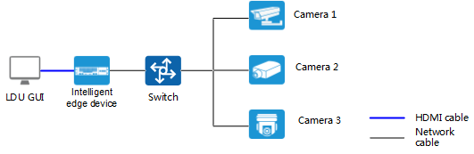
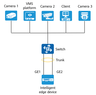
The HWT-IVS1800 supports two network configuration modes: single-address and dual-address.
- Single-address mode: Two network adapters of the HWT-IVS1800 form a bond and are configured with the same IP address.This mode is applicable to scenarios where the cameras, HWT-IVS1800, iClient S100, and VMS platform are on the same network, as shown in Figure 3-140.
To ensure high reliability of the device network or to forward a large amount of data on the network, you need to configure port aggregation for the ports of the switch. For details, see How Do I Configure Port Aggregation?.
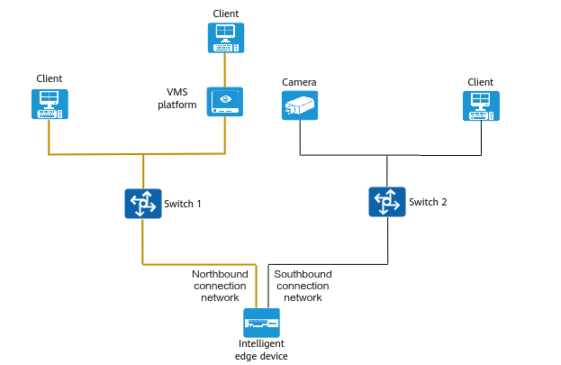
- Dual-address mode: Two network adapters of the HWT-IVS1800 run independently and are configured with IP addresses in different network segments.This mode is applicable to scenarios where the cameras, HWT-IVS1800, iClient S100, and VMS platform are on different networks, as shown in Figure 3-141.
- Cameras can connect to the HWT-IVS1800 only through the southbound connection network.
- The iClient S100 can connect to the HWT-IVS1800 through the northbound connection network and southbound connection network at the same time.
- The VMS platform can connect to the HWT-IVS1800 through either the northbound or southbound connection network.
Setting the Single-Address Mode (on the OMU Portal)
- Log in to the OMU portal as the admin user. ( Logging In to the OMU portal)
- Choose System > Network Configuration.
- Configure the server network, as shown in Figure 3-142. The GUI and parameters vary depending on device models.
Table 3-91 describes the parameters.
Table 3-91 Parameter descriptionParameter
Description
Connection status
Connection status of a network adapter, including
 (connected),
  (disconnected), and
  (to be refreshed).
Name
Network adapter name. The default value is bond0.
Service IP Address
Service IP address, subnet mask, and gateway IP address of the HWT-IVS1800. Set these parameters based on the site requirements.
NOTE:After an IP address is changed, the system automatically restarts some modules, which takes 2 minutes. After the restart, use the new IP address to log in to the OMU portal.
Subnet Mask
Gateway IP Address
Enable IPv6
Indicates whether to enable IPv6. By default, this parameter is deselected.
NOTE:- IPv6 does not support TLS encryption.
- The RESTful interface for server recording playback does not support IPv6.
- IPv6 does not support NAT networking.
- Only IPv6 cameras connected through ONVIF are supported. You can request streams from such cameras.
- Cameras that comply with other protocols, such as HWSDK and GB/T 28181, cannot be connected.
- If the HWT-IVS1800 is connected to the upper-level video and image management platform through GB/T 28181-2016, the HWT-IVS1800 does not support both IPv4 and IPv6 addresses.
Enable DHCPv6
This parameter is available only when Enable IPv6 is selected.
After DHCPv6 is enabled, the IPv6 address information cannot be modified.
Enable DHCPv4
This parameter is available only when Enable IPv6 is deselected.
After DHCPv4 is enabled, the IPv4 address information cannot be modified.
IPv6 Service address
IPv6 network information. Set these parameters based on the site requirements.
NOTE:- The service IP address and gateway IP address must be in the same network segment.
- Changing the IP address will interrupt services. Exercise caution when performing this operation. The restart takes about 1 to 2 minutes.
Ipv6 Subnet Prefix
Ipv6 gateway address
Docker0 IP address
Docker0 IP address. Set this parameter based on the site requirements. The value is in XXX.XXX.X.X/XX format, for example, 114.114.0.0/16. During setting, ensure that no Docker instance is running in the background.
Docker0 IPv6 address
If Enable IPv6 is selected, you need to set the Docker0 IPv6 network information based on the site requirements.

Setting the Single-Address Mode (on the LDU)
- Log in to the LDU as the admin user. ( Logging In to the LDU)
- Click
 in the upper left corner.
 - Choose System > System Settings > Network.
- Configure network information, as shown in Figure 3-143.
Table 3-92 Parameter description
Parameter
Description
IP Address
Service IP address, subnet mask, and gateway IP address of the HWT-IVS1800. Set these parameters based on the site requirements.
NOTE:After an IP address is changed, the system automatically restarts some modules, which takes 2 minutes. After the restart, use the new IP address to log in to the OMU portal.
Subnet Mask
Gateway Address
Enable IPv6
Indicates whether to enable IPv6. By default, this parameter is deselected.
NOTE:- IPv6 does not support TLS encryption.
- The RESTful interface for server recording playback does not support IPv6.
- IPv6 does not support NAT networking.
- Only IPv6 cameras connected through ONVIF are supported. You can request streams from such cameras.
- Cameras that comply with other protocols, such as HWSDK and GB/T 28181, cannot be connected.
- If the HWT-IVS1800 is connected to the upper-level video and image management platform through GB/T 28181-2016, the HWT-IVS1800 does not support both IPv4 and IPv6 addresses.
IPv6 Service address
IPv6 network information. Set these parameters based on the site requirements.
NOTE:- The service IP address and gateway IP address must be in the same network segment.
- Changing the IP address will interrupt services. Exercise caution when performing this operation. The restart takes about 1 to 2 minutes.
Ipv6 Subnet Prefix
IPv6 gateway address
Network Adapter
Select the network adapter for which you need to check the communication status with the target device.
Destination
IP address of the target device to be tested.

Setting the Double-Address Mode (on the OMU Portal)
- Log in to the OMU portal as the admin user. ( Logging In to the OMU portal)
- Choose System > Network Configuration.
- Configure the server network, as shown in Figure 3-144.
Table 3-93 Parameter description
Parameter
Description
Connection status
Connection status of a network adapter, including
 (connected),
  (disconnected), and
  (to be refreshed).
Northbound Network Adapter
The northbound network adapter corresponds to the GE 2 port on the rear panel.
Northbound Service IP Address
Network information of the northbound network adapter. Set these parameters based on the site requirements.
Northbound Subnet Mask
Northbound Gateway IP Address
Southbound Network Adapter
The southbound network adapter corresponds to the GE 1 port on the rear panel.
Southbound Service IP Address
Network information of the southbound network adapter. Set these parameters based on the site requirements.
NOTE:- The southbound and northbound service IP addresses must be on different network segments.
- After an IP address is changed, the system automatically restarts all modules, which takes 2 minutes. After the restart, use the new IP address to log in to the OMU portal.
Southbound Subnet Mask
Southbound Gateway IP Address
Default Route
The default route is the northbound network adapter.
The rules for setting the default route vary depending on whether the IP addresses of the northbound device and northbound network adapter are in the same network segment.
- They are in the same network segment.
- If the IP addresses of the southbound device (for example, a camera) and southbound network adapter are in the same network segment, set the default route to the southbound or northbound network adapter.
- If the IP addresses of the southbound device (for example, a camera) and southbound network adapter are in different network segments, set the default route to the southbound network adapter.
- They are in different network segments.
- If the IP addresses of the southbound device (for example, a camera) and southbound network adapter are in the same network segment, set the default route to the northbound network adapter.
- If the IP addresses of the southbound device (for example, a camera) and southbound network adapter are in different network segments, you are advised to set the default route to the northbound network adapter. In this case, you also need to set the route network segment.
For details about how to configure a specified route network segment, see Maintenance Guide > FAQ > LDU > How Do I Configure a Specified Route Network Segment? in the HWT-IVS1800 Product Documentation.
Route Network Segment
Network segment to which southbound devices belong. If there are multiple network segments, separate them with semicolons (;).
If the iClient S100 and VMS platform are connected through the southbound network, you also need to add the network segments of the iClient S100 and VMS platform.
Docker0 IP address
Docker0 IP address. Set this parameter based on the site requirements. The value is in XXX.XXX.X.X/XX format, for example, 114.114.0.0/16. During setting, ensure that no Docker instance is running in the background.
Enable IPv6
Indicates whether to enable IPv6. By default, this parameter is deselected.
NOTE:- IPv6 does not support TLS encryption.
- The RESTful interface for server recording playback does not support IPv6.
- IPv6 does not support NAT networking.
- Only IPv6 cameras connected through ONVIF are supported. You can request streams from such cameras.
- Cameras that comply with other protocols, such as HWSDK and GB/T 28181, cannot be connected.
- If the HWT-IVS1800 is connected to the upper-level video and image management platform through GB/T 28181-2016, the HWT-IVS1800 does not support both IPv4 and IPv6 addresses.
Northbound service IPv6 address/Southbound IPv6 service address
Network information of the northbound or southbound service. Set these parameters based on the site requirements.
NOTE:- The service IP address and gateway IP address must be in the same network segment.
- Changing the IP address will interrupt services. Exercise caution when performing this operation. The restart takes about 1 to 2 minutes.
Northbound subnet prefix/Southbound Subnet Prefix
IPv6 address of the northbound gateway/Southbound IPv6 gateway address
IPv6 specified route network segment
Information about the IPv6 network segment where the northbound device is located.
If multiple network segments are involved, separate them with semicolons (;) and do not end with a semicolon (;). A maximum of 13 network segments can be configured, and a maximum of 200 characters are supported.

Setting the Double-Address Mode (on the LDU)
- Log in to the LDU as the admin user. ( Logging In to the LDU)
- Click
 in the upper left corner.
 - Choose System > System Settings > Network.
- Configure network information, as shown in Figure 3-145.
Table 3-94 Parameter description
Parameter
Description
Southbound GE1 IP Address/Northbound GE2 IP Address
Network information of a network adapter.
NOTE:- The southbound and northbound service IP addresses must be on different network segments.
- After an IP address is changed, the system automatically restarts some modules, which takes 2 minutes. After the restart, use the new IP address to log in to the OMU portal.
Southbound GE1 Subnet Mask/Northbound GE2 Subnet Mask
Southbound GE1 Gateway Address/Northbound GE2 Gateway Address
Routing Network Segment
Network segment to which the southbound device belongs. If there are multiple network segments, separate them with semicolons (;).
If the iClient S100 and VMS are connected through the southbound network, you also need to add the network segments to which the iClient S100 and VMS belong.
Set GE1 as Default Route
The rules for setting the default route vary depending on whether the IP address of the computer running the northbound device (for example, the iClient S100) and the IP address of the northbound network adapter are in the same network segment.
- They are in the same network segment.
- If the IP addresses of the southbound device (for example, a camera) and southbound network adapter are in the same network segment, set the default route to the southbound or northbound network adapter.
- If the IP addresses of the southbound device (for example, a camera) and southbound network adapter are in different network segments, set the default route to the southbound network adapter.
- They are in different network segments.
- If the IP addresses of the southbound device (for example, a camera) and southbound network adapter are in the same network segment, set the default route to the northbound network adapter.
- If the IP addresses of the southbound device (for example, a camera) and southbound network adapter are in different network segments, you are advised to set the default route to the northbound network adapter. In this case, you also need to set Routing Network Segment.
Set GE2 as Default Route
Enable IPv6
Indicates whether to enable IPv6. By default, this parameter is deselected.
NOTE:- IPv6 does not support TLS encryption.
- The RESTful interface for server recording playback does not support IPv6.
- IPv6 does not support NAT networking.
- Only IPv6 cameras connected through ONVIF are supported. You can request streams from such cameras.
- Cameras that comply with other protocols, such as HWSDK and GB/T 28181, cannot be connected.
- If the HWT-IVS1800 is connected to the upper-level video and image management platform through GB/T 28181-2016, the HWT-IVS1800 does not support both IPv4 and IPv6 addresses.
Northbound service IPv6 address/Southbound IPv6 service address
Network information of the northbound or southbound service. Set these parameters based on the site requirements.
NOTE:- The service IP address and gateway IP address must be in the same network segment.
- Changing the IP address will interrupt services. Exercise caution when performing this operation. The restart takes about 1 to 2 minutes.
Northbound subnet prefix/Southbound Subnet Prefix
IPv6 address of the northbound gateway/Southbound IPv6 gateway address
IPv6 specified route network segment
Information about the IPv6 network segment where the northbound device is located.
If multiple network segments are involved, separate them with semicolons (;) and do not end with a semicolon (;). A maximum of 13 network segments can be configured, and a maximum of 200 characters are supported.
Network Adapter
Select the network adapter for which you need to check the communication status with the target device.
Destination
IP address of the target device to be tested.

Logging in to the Camera Web System
Prerequisites
Cameras have been powered on and connected to the network. For details, see related camera documents.
Procedure
- Enter https://Camera IP address in the Internet Explorer address box, and press Enter.
- Set the password according to instructions during first login. For a non-first login, go to 3.
- Enter the user name and password and click Log In.
The login page varies depending on the camera model.
GB/T 28181 Connection Code Formats
This section describes the formats and meanings of connection codes. Both the local domain code and external domain code are connection codes.
Connection Code Format
The code must consist of 20 digits. Figure 3-146 describes the coding rules.

Figure 3-147 describes the industry codes.

Code Example
Table 3-95 and Table 3-96 describe a local domain code example in domain A and the connection code of a camera shared in domain B.