Others
- How Do I Manually Partition a Disk?
- How Do I Restore a Device to Factory Settings?
- How Do I Reinstall the IVS Service System ?
- How Do I Enter the Private Key Password During System Reinstallation?
- How Do I Log In to the Operating System Through a Serial Port?
- How Do I Log In to the Operating System Through a Network Port?
- How Do I Enable and Disable Local Login to the Database?
- How Do I Connect Cables and Configure Alarm Input and Output Ports?
- What Do I Do If No Signal Is Displayed on a Monitor When It Is Connected to the Device Using the HDMI Port?
- How Do I View the Serial Number of the HWT-IVS1800?
- How Do I View the Specifications of the HWT-IVS1800?
- How Do I View the Verification Code of the HWT-IVS1800?
- What Can I Do If the Device Does Not Respond After Power-on?
- How Do I Power On and Power Off a Device Correctly?
- How Do I Configure Port Aggregation?
- How Do I Check Whether the HWT-IVS1800 Is Properly Connected to the Target Network Environment?
- How Do I Distinguish Disk Partitions?
- Slow Disk Fault Detection
- Cloud Service Interconnection Capability Set
- How Do I Configure the Platform to Display the Video Channel Name as a Camera Name After the HWT-IVS1800 Is Connected to the IVS3800 or IVS2800 Through GB/T 28181?
- How Can I Enable the SSH Function?
- What Can I Do If Live and Recorded Video Cannot Be Properly Played After Data Is Restored in the Subrack Replacement Scenario?
- What Can I Do When Unexpected Power-off Occurs?
- Data Clearance Rules
- How Do I Clear Buzzer Alarms?
- How Do I Enable the Debugging Mode?
- How Do I Set Target Alarms When a Camera Uses the Optimal Capture Mode?
- What Can I Do If the Number of Snapshot Alarms Delivered by the IVS1800 Is Inconsistent with That in the Camera Web System?
- How Do I Handle the Network Communication Failure Caused by the Conflict Between the HWT-IVS1800 and the Docker0 Network Adapter?
- What Can I Do If a Camera Connected to the HWT-IVS1800 Is in Offline State and Fails to Automatically Go Online After It Is Restored to Factory Settings?
- What Can I Do If the Alarm-triggered Recording Is Delayed or Partially Lost?
- What Can I Do If the System Displays a Message Indicating That the Upgrade Fails Due to Invalid Operation When I Perform HWT-IVS1800 Upgrade on the iClient S100?
- What Should I Do If the Upgrade Fails Due to Insufficient Directory Space in Diskless Upgrade Scenarios on the LDU or OMU Portal?
- What Do I Do If Services of Some Modules Cannot Be Started After the Subrack of the HWT-IVS1800 Is Replaced and Data Is Restored Using the Data Safe?
- How Do I Check the Available Space of the /home Directory?
- What Do I Do If the VA Algorithm Plug-in Fails to Be Installed Due to Insufficient Space of the /home Directory?
- How Do I Restore a Saved Recording File That Is Lost in RAID Mode?
- How Do I Improve the Detection Rate of an Inspection Large Model Algorithm?
- How Do I Reduce the False Positive Rate of an Inspection Large Model Algorithm?
- How Do I Determine Whether the Current Object Size Meets the Specifications of an Inspection Large Model Algorithm?
- What Do I Do If No Alarm Is Reported for the Cloud Service?
How Do I Manually Partition a Disk?
Symptom
- On the disk management page of the OMU portal, a RAID 5 group is degraded, in which a disk encounters a file system error.
- Run the lsblk command in the background and verify that sdb (assume that the name of the disk whose partition table is lost is sdb) has no partition.

Root Cause
The SafeVideo cannot identify the disk whose partition table is lost. As a result, the RAID 5 group is degraded.
Procedure
- Run the cat /home/ivs_common/public/diskinfo.xml | grep AlgSize command to check the value of DiskThdAlgSize.

- Execute the partitioning script with the disk name as the first input parameter and DiskThdAlgSize as the second input parameter, for example, bash /home/ivstool/init.d/partedtwo.sh /dev/sdb 23.

- After the partitioning is complete, wait for about 5 minutes and check whether the disk status is normal or data is synchronized on the OMU portal.
How Do I Restore a Device to Factory Settings?
Important Notes

Restoring factory settings may pose risks. Exercise caution when performing this operation.
Table 6-35 describes the impact of restoring factory settings on software versions and service data.
Device Type |
Impact on Software Versions |
Impact on Service Data |
|---|---|---|
|
|
Context
The following describes how a device is restored to factory settings:
- Press and hold the reset button on the rear panel for 10 seconds.
The buzzer buzzes for 2 seconds, indicating that the device enters the mode for restoring factory settings.
- Wait about 1 to 2 minutes for the PWR indicator on the front panel to turn from steady green to steady yellow, and the buzzer to produce two beeps (two seconds in total).
In this case, the device starts to restore factory settings.
- Several minutes later, the PWR indicator on the front panel turns from steady yellow to steady green, and the buzzer buzzes for three times (3 seconds in total).
In this case, the device is restored to factory settings.
- It takes about 18 minutes to restore the HWT-IVS1800-E or HWT-IVS1800-D to factory settings.
Procedure
The operations are similar for all HWT-IVS1800 models. This section uses the HWT-IVS1800-E08 as an example.
- Remove the network cable from the network port of the device to ensure that the device is disconnected from the network.
After the device is restored to factory settings, the default IP address changes to 192.168.3.111. If the network is not disconnected and the IP address 192.168.3.111 exists on the network, the factory setting restoration fails due to an IP address conflict.
- Ensure that the device is running, as shown in Figure 6-117.
- The power switch is turned on (in I state).
- Use a needle-type object to press and hold down the reset button for 10s, as shown in Figure 6-118.
The device automatically restarts after being restored to factory settings.
- It takes about 18 minutes to restore the HWT-IVS1800-E or HWT-IVS1800-D to factory settings.
- Determine whether to restore disk data (including recordings).
- Restore disk data.

Before restoring disk data, you need to install the software whose version is that of the device software before factory settings restoration.
- Sufficient disk space is required for the upgrade. However, the disk is used for data restoration. Therefore, the upgrade cannot be performed.
- After the Data Safe restoration is successfully performed, the passwords of the operating system and service system users are automatically restored to the passwords set before the factory setting restoration.
- Based on the LDU
Configure the initialization service by referring to Configuring the Startup Wizard. When the system displays a message asking you whether to restore disk-backup data, click Yes.
You do not need to perform initialization on the RAID configuration page.
- Based on the OMU portal
- Connect the computer directly to the device, and set the computer to be in the same network segment (192.168.3.111/24) as the device.
- Configure the IP address by referring to Setting Network Parameters.
- Restore data using the Data Safe by referring to Restoring Data Using the Data Safe.
- Format the disk without restoring disk data.
- Based on the LDU
Configure the initialization service by referring to Configuring the Startup Wizard. When the system displays a message asking you whether to restore disk-backup data, click No.
You need to perform initialization on the RAID configuration page.
- Based on the OMU portal
- Connect the computer directly to the device, and set the computer to be in the same network segment (192.168.3.111/24) as the device.
- Configure the IP address by referring to Setting Network Parameters.
- Initialize the disk by referring to Initializing Disks.
- Based on the LDU
- Restore disk data.
- Connect the network cable to the network port of the device to ensure that the device is connected to the network.


How Do I Reinstall the IVS Service System ?
Context
The following describes how the device system is reinstalled:
- Run the install.sh script.
- Wait about 1 to 2 minutes for the PWR indicator on the front panel to turn from steady green to steady yellow, and the buzzer to produce two beeps (two seconds in total).
The device system starts to be reinstalled.
- Wait about 15 minutes for the PWR indicator on the front panel to turn from steady yellow to steady green, and the buzzer to produce three beeps (3 seconds in total).
The device system reinstallation is complete.
Important Notes
If you reinstall the IVS service system, all configuration data will be lost, and the passwords of the service system user will be reset. However, the operating system passwords will be retained.
Procedure (Script Mode)
- Install the IVS service system in the operating system.
- Log in to the operating system as the root user. (
 How Do I Log In to the Operating System Through a Network Port?)
 - Delete temporary files and create an installation directory.
bash /home/ivstool/bin/prepare_ftp_dir.sh
- Upload _12.0.0.SPC30_Full.zip or _12.0.0.SPC30_Full.zip to /home/tmp.
- Decompress the installation package.
bash /home/ivstool/bin/unzip_install_file.sh
- Install the service system.
Use the single-address mode as an example.
cd /micro_cloud_install/script
bash install.sh 192.168.6.200 192.168.6.1
In the preceding information, 192.168.6.200 and 192.168.6.1 indicate the IP address and gateway address of the device before system reinstallation, respectively.
To view the IP address and gateway address of the device, log in to the OMU portal of the device as the admin user, choose , and check the IP address and gateway address of the device in the network adapter configuration area.
For a device that uses the dual-address mode before system reinstallation, you can use the IP address and gateway address of either the northbound or southbound network adapter when running the installation script. After successful system reinstallation, the network mode of the device changes to the single-address mode, and the IP address and gateway address are those of the network adapter used during reinstallation.
Assume that the IP address and gateway address of the northbound network adapter are 10.10.10.10 and 10.10.10.1 respectively, and those of the southbound network adapter are 192.168.6.200 and 192.168.6.1 respectively. If you run the bash install.sh 10.10.10.10 10.10.10.1 script during system reinstallation in this case, the network mode of the device changes to the single-address mode and the IP address and gateway address are 10.10.10.10 and 10.10.10.1 respectively after reinstallation.
The system automatically installs the service system, which takes about 15 minutes.
If information similar to the following is displayed, the installation is successful:
...
...
[2020-01-13 23:21:55 +0800] INFO: Start Gaussdb successful!
[2020-01-13 23:21:55 +0800] INFO: Start SCU successful!
[2020-01-13 23:21:55 +0800] INFO: Start SMU successful!
[2020-01-13 23:21:55 +0800] INFO: Start DCG successful!
[2020-01-13 23:21:55 +0800] INFO: Start OMU successful!
[2020-01-13 23:21:55 +0800] INFO: Start MU successful!
[2020-01-13 23:21:56 +0800] INFO: Start LDU successful!
[2020-01-13 23:21:56 +0800] INFO: Start IMGU successful!
[2020-01-13 23:21:56 +0800] INFO: Start MCS successful!
[2020-01-13 23:21:56 +0800] INFO: Start OMUPORTAL successful!
[2020-01-13 23:21:56 +0800] INFO: Start VA successful!
[2020-01-13 23:21:56 +0800] INFO: Start PCG successful!
[2020-01-13 23:21:56 +0800] INFO: Start SIP successful!
[2020-01-13 23:21:56 +0800] INFO: Start OCG successful!
successful process:15  install successful!
During the installation, the operating system automatically exits if you do not perform any operations within a specified period of time. In this case, you can view the installation log file in /home/install/log/install.- In the name of an installation log (in install_XXXXXXXXXXXXXX.log naming format), XXXXXXXXXXXXXX indicates the timestamp. Check the latest installation log based on the timestamp.
- Files named installXXX.log are the installation logs of each module.
- (Optional) Set the password of the ivsoper user if you want to obtain exception locating information, such as logs of each module, as the ivsoper user.
After the service system is reinstalled, the ivsoper user is disabled and the password of the ivsoper user is cleared. You need to perform the following substeps:
- Enable the ivsoper user so that the ivsoper user can be used to log in to the service system.
usermod -s /bin/bash ivsoper
- Log in to the service system as admin first and then switch to the ivsoper user if the ivsoper user cannot be used to directly log in to the service system.
sed -i '/^DenyUsers ivsoper/d' /etc/ssh/sshd_config
sed -i '/DenyUsers root/a DenyUsers ivsoper' /etc/ssh/sshd_config
- Set the password of the ivsoper user.
Euler:~ # passwd ivsoper
Changing password for user ivsoper.
New password:
Retype new password:
- Assign permissions to the ivsoper user.
setfacl -m u:ivsoper:0 /usr/bin/python 2> /dev/null
setfacl -m u:ivsoper:0 /usr/bin/python3 2> /dev/null
setfacl -m u:ivsoper:0 /usr/bin/python3.7 2> /dev/null
setfacl -m u:ivsoper:0 /usr/bin/python3.7m 2> /dev/null
iptables -A OUTPUT -p all -m owner --uid-owner ivsoper -j DROP
- Enable the ivsoper user so that the ivsoper user can be used to log in to the service system.
- Log in to the operating system as the root user. (
Procedure (General Mode)
- Install the IVS service system in the operating system.
- Log in to the operating system as the root user. ( How Do I Log In to the Operating System Through a Network Port?)
- Delete temporary files.
cd /home/install
rm -rf `ls /home/install | egrep -v '(cert|EncryptXml|oem_out.zip)'`
- Upload _12.0.0.SPC30_Full.zip or _12.0.0.SPC30_Full.zip to /tmp.
- Move _12.0.0.SPC30_Full.zip or _12.0.0.SPC30_Full.zip to /micro_cloud_install.
mv /tmp/_12.0.0.SPC30_Full.zip or _12.0.0.SPC30_Full.zip /micro_cloud_install
- Decompress and delete _12.0.0.SPC30_Full.zip or _12.0.0.SPC30_Full.zip.
cd /micro_cloud_install
unzip _12.0.0.SPC30_Full.zip or _12.0.0.SPC30_Full.zip
rm _12.0.0.SPC30_Full.zip or _12.0.0.SPC30_Full.zip
The _12.0.0.SPC30_Full.zip or _12.0.0.SPC30_Full.zip package must be deleted. Otherwise, the installation will fail due to insufficient device space.
- Decompress and delete _12.0.0.SPC30Full.zip or _12.0.0.SPC30Full.zip.
unzip _12.0.0.SPC30Full.zip or _12.0.0.SPC30Full.zip
rm _12.0.0.SPC30Full.zip or _12.0.0.SPC30Full.zip
The _12.0.0.SPC30Full.zip or _12.0.0.SPC30Full.zip package must be deleted. Otherwise, the installation will fail due to insufficient device space.
- Install the service system.
Use the single-address mode as an example.
cd /micro_cloud_install/script
bash install.sh 192.168.6.200 192.168.6.1
In the preceding information, 192.168.6.200 and 192.168.6.1 indicate the IP address and gateway address of the device before system reinstallation, respectively.
To view the IP address and gateway address of the device, log in to the OMU portal of the device as the admin user, choose , and check the IP address and gateway address of the device in the network adapter configuration area.
For a device that uses the dual-address mode before system reinstallation, you can use the IP address and gateway address of either the northbound or southbound network adapter when running the installation script. After successful system reinstallation, the network mode of the device changes to the single-address mode, and the IP address and gateway address are those of the network adapter used during reinstallation.
Assume that the IP address and gateway address of the northbound network adapter are 10.10.10.10 and 10.10.10.1 respectively, and those of the southbound network adapter are 192.168.6.200 and 192.168.6.1 respectively. If you run the bash install.sh 10.10.10.10 10.10.10.1 script during system reinstallation in this case, the network mode of the device changes to the single-address mode and the IP address and gateway address are 10.10.10.10 and 10.10.10.1 respectively after reinstallation.
The system automatically installs the service system, which takes about 15 minutes.
If information similar to the following is displayed, the installation is successful:
...
...
[2020-01-13 23:21:55 +0800] INFO: Start Gaussdb successful!
[2020-01-13 23:21:55 +0800] INFO: Start SCU successful!
[2020-01-13 23:21:55 +0800] INFO: Start SMU successful!
[2020-01-13 23:21:55 +0800] INFO: Start DCG successful!
[2020-01-13 23:21:55 +0800] INFO: Start OMU successful!
[2020-01-13 23:21:55 +0800] INFO: Start MU successful!
[2020-01-13 23:21:56 +0800] INFO: Start LDU successful!
[2020-01-13 23:21:56 +0800] INFO: Start IMGU successful!
[2020-01-13 23:21:56 +0800] INFO: Start MCS successful!
[2020-01-13 23:21:56 +0800] INFO: Start OMUPORTAL successful!
[2020-01-13 23:21:56 +0800] INFO: Start VA successful!
[2020-01-13 23:21:56 +0800] INFO: Start PCG successful!
[2020-01-13 23:21:56 +0800] INFO: Start SIP successful!
[2020-01-13 23:21:56 +0800] INFO: Start OCG successful!
successful process:15  install successful!
During the installation, the operating system automatically exits if you do not perform any operations within a specified period of time. In this case, you can view the installation log file in /home/install/log/install.
- In the name of an installation log (in install_XXXXXXXXXXXXXX.log naming format), XXXXXXXXXXXXXX indicates the timestamp. Check the latest installation log based on the timestamp.
- Files named installXXX.log are the installation logs of each module.
If you need to restore data after the IVS service system is reinstalled, you need to ensure that the service system version before reinstallation is the same as that after reinstallation.
- (Optional) Set the password of the ivsoper user if you want to obtain exception locating information, such as logs of each module, as the ivsoper user.
After the service system is reinstalled, the ivsoper user is disabled and the password of the ivsoper user is cleared. You need to perform the following substeps:
- Enable the ivsoper user so that the ivsoper user can be used to log in to the service system.
usermod -s /bin/bash ivsoper
- Log in to the service system as admin first and then switch to the ivsoper user if the ivsoper user cannot be used to directly log in to the service system.
sed -i '/^DenyUsers ivsoper/d' /etc/ssh/sshd_config
sed -i '/DenyUsers root/a DenyUsers ivsoper' /etc/ssh/sshd_config
- Set the password of the ivsoper user.
Euler:~ # passwd ivsoper
Changing password for user ivsoper.
New password:
Retype new password:
- Assign permissions to the ivsoper user.
setfacl -m u:ivsoper:0 /usr/bin/python 2> /dev/null
setfacl -m u:ivsoper:0 /usr/bin/python3 2> /dev/null
setfacl -m u:ivsoper:0 /usr/bin/python3.7 2> /dev/null
setfacl -m u:ivsoper:0 /usr/bin/python3.7m 2> /dev/null
iptables -A OUTPUT -p all -m owner --uid-owner ivsoper -j DROP
- Enable the ivsoper user so that the ivsoper user can be used to log in to the service system.
- Log in to the operating system as the root user. (
- Determine whether to restore disk data (including recordings).
- Restore disk data.
Before starting disk data restoration, you need to ensure that the service system version before reinstallation is the same as that after reinstallation.
- Based on the LDU
Configure the initialization service by referring to Configuring the Startup Wizard. When the system displays a message asking you whether to restore disk-backup data, click Yes.
You do not need to perform initialization on the RAID configuration page.
- Based on the OMU portal
- Configure the IP address by referring to Setting Network Parameters.
- Restore data using the Data Safe by referring to Restoring Data Using the Data Safe.
- Based on the LDU
- Format the disk without restoring disk data.
- Based on the LDU
Configure the initialization service by referring to Configuring the Startup Wizard. When the system displays a message asking you whether to restore disk-backup data, click No.
You need to perform initialization on the RAID configuration page.
- Based on the OMU portal
- Configure the IP address by referring to Setting Network Parameters.
- Initialize the disk by referring to Initializing Disks.
- Based on the LDU
- Restore disk data.
How Do I Enter the Private Key Password During System Reinstallation?
Context
When you reinstall the service system in the operating system, the system prompts you to enter the private key password after you execute the install.sh script.
Solution
- When the system displays the following information:
Enter your oem passwd:
Enter the private key password 6UKTW1VQMDL.
If you do not enter the private key password within 60 seconds, the system automatically logs out and the installation script stops. When you reinstall the service system next time, you still need to perform this step.
- Perform other required reinstallation steps.
How Do I Log In to the Operating System Through a Serial Port?
Prerequisites
- An RS-232 serial cable has been prepared.
- PuTTY has been installed on a computer.
Context
To perform operations as the root/ivsoper user, log in as the admin user and then switch to the root/ivsoper user, instead of directly logging in as the root/ivsoper user.
Procedure
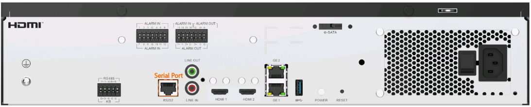
- Use an RS-232 serial cable to connect the device to the computer.
Figure 6-119 shows the serial port on the device.
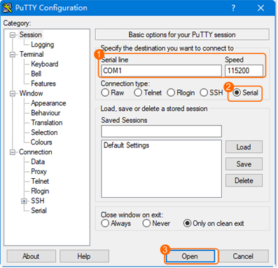
- Double-click
 to start PuTTY.
 - Connect to the device through a serial port and set Speed to 115200, as shown in Figure 6-120.
To view the port, choose Computer Management > Device Manager > Ports (COM & LPT).
- Enter the user name admin and the password, and press Enter.
Authorized users only. All activities may be monitored and reported.
Euler login: admin
Password:
Last login: Wed Feb 26 15:58:10 from 192.168.1.100
Authorized users only. All activities may be monitored and reported.
Euler:~ #
- Switch to the root user.
su - root
Enter the password of the root user during command execution.
- Set the login passwords for the root and admin users upon the first login to the operating system.
For details about how to change the passwords, see Changing the Password (CLI).
How Do I Log In to the Operating System Through a Network Port?
Context
To perform operations as the root/ivsoper user, log in as the admin user and then switch to the root/ivsoper user, instead of directly logging in as the root/ivsoper user.
Procedure
- Enable the SSH function.
For security purposes, the SSH function is disabled by default. For details about how to enable the SSH function, see How Can I Enable the SSH Function?.
- Enter the IP address and admin in the SSH connection tool and press Enter.
- If you have not set the OS password in the LDU or OMU portal startup wizard, you need to enter the default password upon the first login before changing the password. For details about the default password, see the HWT-IVS1800 Account List.
- If you have set the OS password in the LDU or OMU portal startup wizard, you need to enter the preset password when logging in to the OS for the first time.
WARNING: Your password has expired.
Your must change your password now and login again!
Changing password for user admin.
Current password: // Enter the initial password.
New password: // Enter the new password of the admin user of the OS, for example, 1qaz@WSX#EDC.
Retype new password: // Enter the new password again, for example, 1qaz@WSX#EDC.
- Switch to the root or ivsoper user. Switch to the desired user based on the actual service scenario.
- Run the su - root command to switch to the root user.
Enter the password of the root user during command execution.
- Run the su - ivsoper command to switch to the ivsoper user.
Enter the password of the ivsoper user during command execution.
- Run the su - root command to switch to the root user.
How Do I Enable and Disable Local Login to the Database?
Context
If a fault occurs on a device and cannot be located, you can log in to the local database to determine the fault cause.
Procedure
- Log in to the operating system as the root user. ( How Do I Log In to the Operating System Through a Network Port?)
- Stop the service processes of the database.
sh /home/ivstool/bin/service.sh stop gsdb
- Run the vi /home/gaussdba/app/data/cfg/zengine.ini command to open the configuration file.
- Modify the configuration file.
- Press i to enter the editing mode.
- Find ENABLE_SYSDBA_LOGIN = FALSE in the configuration file and change the value of ENABLE_SYSDBA_LOGIN to TRUE.
LSNR_PORT = 6000
LSNR_ADDR = 127.0.0.1
INSTANCE_NAME = zenith
DATA_BUFFER_SIZE = 256M
SHARED_POOL_SIZE = 82M
TEMP_BUFFER_SIZE = 32M
LOG_BUFFER_SIZE = 4M
DBWR_PROCESSES = 1
LOG_BUFFER_COUNT = 4
SESSIONS = 111
_SYS_PASSWORD = I3/25wUA0Af3fvk7fSCmCXMMZrNBjR2WGk7d3xJvDiCD+MQPta5x1Xq1ip5nmukdPvCrT9LZHGlqY1rFNUxkULc2rNp5xiypkW35dDCjaVkU18EUvkqfNQ==
EMPTY_STRING_AS_NULL = FALSE
LOG_HOME = /home/gaussdba/app/data/log
_AGENT_STACK_SIZE = 1M
_LOG_LEVEL = 7
_LOG_MAX_FILE_SIZE = 1M
_LOG_BACKUP_FILE_COUNT = 10
MAX_ARCH_FILES_SIZE = 100M
ARCH_CLEAN_IGNORE_BACKUP = TRUE
ARCH_CLEAN_IGNORE_STANDBY = TRUE
LOCAL_KEY = x4nWCzyTc4GmUgu87imYM1RuZnqYmWstalD/LxDxRAHA8oYITB+ohmL/KDkS8hjj2UjI4a831D6i5YlvKDgv4g==
CONTROL_FILES = (/DB_DATA/data/data/cntl1, /DB_DATA/data/data/cntl2, /DB_DATA/data/data/cntl3)
RESOURCE_LIMIT = TRUE
TCP_INVITED_NODES = (127.0.0.1/32)
TCP_EXCLUDED_NODES = (192.168.3.0/24)
TCP_VALID_NODE_CHECKING = TRUE
CPU_NODE_BIND = 0 3
WORKER_THREADS_SHRINK_THRESHOLD = 300
OPTIMIZED_WORKER_THREADS = 50
MAX_WORKER_THREADS = 60
SUPER_USER_RESERVED_SESSIONS = 2
_SYSTIME_INCREASE_THREASHOLD = 0
ENABLE_SYSDBA_LOGIN = FALSE
Press Esc to exit the editing mode.
Run the :wq command to save the configurations and exit.
- Switch the user to gaussdba.
su - gaussdba -s /bin/bash
- Start the database service.
cd /home/gaussdba/app/bin
python zctl.py -t start
- Log in to the database.
zsql / as sysdba
[gaussdba@Euler bin]$ zsql / as sysdba
Warning: SSL connection to server without CA certificate is insecure. Continue anyway? (y/n):y
- Use the GaussDB by referring to the corresponding product documentation.
- Disable the login to the local database.
- Exit the database.
exit
- Exit the gaussdba user.
exit
- Disable the login to the local database.
sh /home/ivstool/bin/service.sh restart gsdb
- Exit the database.
How Do I Connect Cables and Configure Alarm Input and Output Ports?
Context
- This section describes how to connect alarm input and output ports on the HWT-IVS1800 and how to configure I/O alarms and alarm linkage for the HWT-IVS1800 and cameras.
- For details about how to connect to the alarm input and output ports of a camera, see the quick start guide of the corresponding camera model. You can visit http://www.holowits.com/documentation, search for the camera by model or keyword, and obtain the required document.
Model Restrictions
I/O alarms cannot be configured for devices connected through GB/T 28181.
Connecting to Alarm Input/Output Ports
- Port description
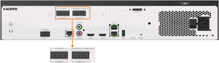
- Ports with the ALARM IN labels are alarm input ports, which can be connected to a maximum of 16 alarm input devices.
- Ports 1+/1-, 2+/2-, 3+/3-, and 4+/4- with the ALARM OUT labels are alarm output ports, which can be connected to a maximum of four alarm output devices.
The sign + indicates high-level output, and - indicates low-level output. For example, port 1+ is used for high-level output of line 1, and port 1- for low-level output of line 1.
- Port G is the ground port, which is used with the alarm input and output ports. One ground port can be used to ground multiple alarm input and output ports at the same time.
- Alarm output connection
This section describes only the alarm output connection mode, which is similar to the alarm input connection mode. To enable alarm input, you need to connect the cable of an alarm input device to the slot of alarm input port 1, 2, 3, or 4 on the rear panel of the device corresponding to the Phoenix connector, and connect the ground cable to the ground port.

Configuring HWT-IVS1800 I/O Alarms (Based on the LDU)
- Log in to the LDU as the admin user. (
 Logging In to the LDU)
 - Click
 in the upper left corner to access the main menu.
 - Choose System Management > System Settings > Boolean Value.
- Configure alarm input.
- On the Alarm-in tab page, click
 in the Edit Alarm Input column, set alarm input parameters, and click Apply, as shown in Figure 6-121.
- (Optional) Click Apply To, select the alarm input ID to which you want to copy the current parameter settings, and click Save.
- On the Alarm-in tab page, click
 in the Edit Alarm column and set alarm linkage parameters as required. The following uses Preset Position Configuration as an example.
 - Toggle on Invoke Preset Position and click Preset Position Configuration. In the dialog box that is displayed, configure a preset position and click Save. Then click Apply. Figure 6-122 shows the process for configuring a preset position.
- (Optional) Click Apply To, select the alarm input ID to which you want to copy the current parameter settings, and click Save.
Table 6-36 describes the key parameters.
Table 6-36 Alarm input parametersArea
Parameter
Description
Alarm-in
Alarm Input Number
Alarm input channel ID.
- The HWT-IVS1800 supports a maximum of 16 alarm input devices.
Alarm Name
Name of an I/O alarm input channel.
Mode
Alarm input status. Set this parameter based on the attribute of the port connected to the alarm device. If no alarm device is connected, set Mode to Close.
- Normally open
Alarm input is switched off by default. For example, when ports 1 and G are short-circuited, the I/O input alarm is continuously generated. The alarm can link the camera to perform predefined actions such as video recording and snapshot taking.
- Normally close
Alarm input is switched on by default. For example, when ports 1 and G are disconnected, the I/O input alarm is continuously generated.
- Close
Alarm input is disabled.
Alarm Interval (s)
Alarm input interval, in seconds.
The value ranges from 1 to 3600.
Setting Alarm Linkage
Recording/Stop Recording/Alarm Output/Triggered Snapshot/Invoke Preset Position/Send Email
Indicates whether to enable an alarm linkage action.
Video Camera/Stop Camera/Snapshot Camera
Camera to be linked to record video when an alarm is triggered. You can set this parameter based on the site requirements.
When an alarm is triggered, the selected cameras start to record video, stop video recording, or take snapshots.
Recording Duration(s)
Customized alarm linkage duration.
The value ranges from 1 to 3600, in seconds.
Alarm Output ID
Alarm output channel ID.
Preset Position Configuration
Button for configuring a preset position. After clicking this button, you can select the camera to be linked and configure a preset position in the dialog box that is displayed. When a service alarm is generated, the linked camera stops at the preset position.
Email Settings
Button for configuring the email address. After clicking this button, you can configure the email address of the recipient in the dialog box that is displayed. When an alarm is generated, an email is sent to the configured email address.
- On the Alarm-in tab page, click
- Configure alarm output.
- On the Alarm-out tab page, click
 in the Edit Alarm Output column, set alarm output parameters, and click OK, as shown in Figure 6-123.
Table 6-37 describes the key parameters.
Table 6-37 Alarm output parametersArea
Parameter
Description
Alarm-out
Alarm Output
Alarm output channel ID.
- The HWT-IVS1800 supports a maximum of four alarm output devices.
Mode
Alarm output status. Set this parameter based on the attribute of the port connected to the alarm device. If no alarm device is connected, set Mode to Close.
- Normally close
Alarm output is switched on by default, and ports 1+ and 1- are short-circuited. When the alarm output device is linked, ports 1+ and 1- are disconnected.
- Normally open
Alarm output is switched off by default, and the ports 1+ and 1- are disconnected.
When the alarm output device is linked, ports 1+ and 1- are short-circuited.
- Close
Alarm output is disabled.
Alarm Name
Name of an I/O alarm output channel.
Display
Alarm output duration.
The value ranges from 1 to 3600, in seconds.
- On the Alarm-out tab page, click


Configuring HWT-IVS1800 I/O Alarms (Based on the OMU Portal)
This section describes how to enable the I/O alarm function on the HWT-IVS1800. For details about how to configure I/O alarm linkage, see Configuring HWT-IVS1800 I/O Alarms (Based on the LDU) or iClient S100 User Manual.
- Log in to the OMU portal as the admin user. (
 Logging In to the OMU portal)
 - Choose System > I/O Settings.
- Set I/O alarm parameters, as shown in Figure 6-124.
Table 6-38 describes the key parameters.
Table 6-38 Parameter descriptionArea
Parameter
Description
Alarm Input
Name
Name of an I/O alarm input channel.
- The IVS1800 supports a maximum of 16 alarm input devices.
Type
Alarm input status. Set this parameter based on the attribute of the port connected to the alarm device. If no alarm device is connected, set Type to Close.
- Normally open
Alarm input is switched off by default. For example, when ports 1 and G are short-circuited, the I/O input alarm is continuously generated. The alarm can link the camera to perform predefined actions such as video recording and snapshot taking.
- Normally close
Alarm input is switched on by default. For example, when ports 1 and G are disconnected, the I/O input alarm is continuously generated.
- Close
Alarm input is disabled.
Alarm Interval
Interval between two alarms.
Alarm Output
Name
Name of an alarm output channel.
- The IVS1800 supports a maximum of four alarm output devices.
Type
Alarm output status. Set this parameter based on the attribute of the port connected to the alarm device. If no alarm device is connected, set Type to Close.
- Normally close
Alarm output is switched on by default, and ports 1+ and 1- are short-circuited. When the alarm output device is linked, ports 1+ and 1- are disconnected.
- Normally open
Alarm output is switched off by default, and the ports 1+ and 1- are disconnected. When the alarm output device is linked, ports 1+ and 1- are short-circuited.
- Close
Alarm output is disabled.
Duration
I/O alarm output duration.
The value ranges from 1 to 3600, in seconds.

Configuring Camera I/O Alarms (Based on the LDU)
- Log in to the LDU as the admin user. ( Logging In to the LDU)
- Click in the upper left corner to access the main menu.
- Choose .
- Configure alarm input.
- On the Alarm-in tab page, click
 in the Edit Alarm Input column, set alarm input parameters, and click Apply, as shown in Figure 6-125.
- (Optional) Click Apply To, select the alarm input ID to which you want to copy the current parameter settings, and click Save.
- On the Alarm-in tab page, click
 in the Edit Alarm column and set alarm linkage parameters as required. The following uses Preset Position Configuration as an example.
 - Toggle on Invoke Preset Position and click Preset Position Configuration. In the dialog box that is displayed, configure a preset position and click Save. Then click Apply. Figure 6-126 shows the process for configuring a preset position.
- (Optional) Click Apply To, select the alarm input ID to which you want to copy the current parameter settings, and click Save.
Table 6-39 describes the key parameters.
Table 6-39 Alarm input parametersArea
Parameter
Description
Alarm-in
Alarm Input Number
Alarm input channel ID.
- The HWT-IVS1800 supports a maximum of 16 alarm input devices.
Alarm Name
Name of an I/O alarm input channel.
Mode
Alarm input status. Set this parameter based on the attribute of the port connected to the alarm device. If no alarm device is connected, set Mode to Close.
- Normally open
Alarm input is switched off by default. For example, when ports 1 and G are short-circuited, the I/O input alarm is continuously generated. The alarm can link the camera to perform predefined actions such as video recording and snapshot taking.
- Normally close
Alarm input is switched on by default. For example, when ports 1 and G are disconnected, the I/O input alarm is continuously generated.
- Close
Alarm input is disabled.
Check Interval (s)
Alarm input interval, in seconds.
The value ranges from 1 to 3600.
Setting Alarm Linkage
Recording/Stop Recording/Alarm Output/Triggered Snapshot/Invoke Preset Position/Send Email
Indicates whether to enable an alarm linkage action.
Channel/Channel/Snapshot channel
Camera to be linked to record video when an alarm is triggered. You can set this parameter based on the site requirements.
When an alarm is triggered, the selected cameras start to record video, stop video recording, or take snapshots.
Recording Duration(s)/Duration(s)
Customized recording or alarm linkage duration. The alarm linkage duration ranges from 1 to 3600, in seconds.
- The default recording duration is 60s. You are advised to set this parameter to a value greater than or equal to 60s.
Channel ID
Alarm output channel ID.
Preset Position Configuration
Button for configuring a preset position. After clicking this button, you can select the camera to be linked and configure a preset position in the dialog box that is displayed. When a service alarm is generated, the linked camera stops at the preset position.
Email Settings
Button for configuring the email address. After clicking this button, you can configure the email address of the recipient in the dialog box that is displayed. When an alarm is generated, an email is sent to the configured email address.
- On the Alarm-in tab page, click
- Configure alarm output.
- On the Alarm-out tab page, click
 in the Edit Alarm Output column, set alarm output parameters, and click Apply, as shown in Figure 6-127.
- (Optional) Click Apply To, select the alarm output ID to which you want to copy the current parameter settings, and click Save.
Table 6-40 describes the key parameters.
Table 6-40 Alarm output parametersArea
Parameter
Description
Alarm-out
Alarm Output ID
Alarm output channel ID.
- The HWT-IVS1800 supports a maximum of four alarm output devices.
Alarm Name
Name of an I/O alarm output channel.
Display Duration (s)
Alarm output duration.
The value ranges from 1 to 3600, in seconds.
- On the Alarm-out tab page, click


What Do I Do If No Signal Is Displayed on a Monitor When It Is Connected to the Device Using the HDMI Port?
Symptom
No signal is displayed on a monitor when it is connected to the device using the HDMI port.

Possible Causes
- The HDMI port is abnormal. In this case, the device needs to be restarted.
- The HDMI port is in poor contact. In this case, you need to remove and insert the HDMI cable again.
Solution
- Remove and insert the HDMI cable or insert it into another HDMI port. Ports HDMI1 and HDMI2 support a maximum resolution of 4K.
If the fault persists or if two monitors are used on site, go to the next step.
- Restart the device.
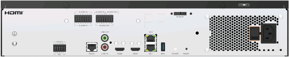
- Press and hold down the POWER button for more than 10 seconds to power off the device, as shown in Figure 6-129.
- Press the POWER button again to restart the device.

How Do I View the Serial Number of the HWT-IVS1800?
Procedure
Check the serial number label attached to the device.
- Log in to the OMU portal.
- Log in to the OMU portal as the admin user. ( Logging In to the OMU portal)
- On the page that is displayed, choose .
- Scan the QR code to add the device and view the device serial number.
In the device information, SN indicates the serial number of the device.
- Log in to the OMU portal as the admin user. (
Log in to the HWT-IVS1800 and query the serial number.
- Log in to the operating system as the root user. ( How Do I Log In to the Operating System Through a Network Port?)
- Query the serial number.
elabel get 0x11
- Log in to the operating system as the root user. (
How Do I View the Specifications of the HWT-IVS1800?
Procedure
Check the specifications label attached to the device.
- LDU:
- Log in to the LDU as the admin user. ( Logging In to the LDU)
- Click in the upper left corner to access the main menu.
- Choose System Management > System Info.
- View the device information. The following figure uses HWT-IVS1800-E as an example, as shown in Figure 6-130.
- Log in to the LDU as the admin user. (
- OMU portal:
- Log in to the OMU portal as the admin user. ( Logging In to the OMU portal)
- View device information on the home page.
- Log in to the OMU portal as the admin user. (
Log in to the and query device specifications.
- Log in to the operating system as the root user. ( How Do I Log In to the Operating System Through a Network Port?)
- View device specifications.
elabel get 0x10
- Log in to the operating system as the root user. (

How Do I View the Verification Code of the HWT-IVS1800?
Procedure
- OMU portal:
- Log in to the OMU portal as the admin user. ( Logging In to the OMU portal)
- On the page that is displayed, choose .
- Scan the QR code to add the IVS1800 and view the verification code.
- Log in to the OMU portal as the admin user. (
What Can I Do If the Device Does Not Respond After Power-on?
The method described in this section applies only to IVS1800-D series.
Symptom
The recovery method described in this section can be performed only when the following conditions are met:
- After the device is powered on, no information is displayed on the LDU.
- The device cannot be pinged on a computer in the same network environment.
If the dual-address mode is enabled on the device, both IP addresses cannot be pinged.
- You cannot use the SSH connection tool to log in to the operating system through a network port.
For details about how to log in to the operating system through a network port, see How Do I Log In to the Operating System Through a Network Port?.
- You cannot log in to the operating system through a serial port.
For details about how to log in to the operating system through a serial port, see How Do I Log In to the Operating System Through a Serial Port?.
Important Notes
If you want to use the method provided in this section to restore the device after the preceding faults occur, pay attention to the following precautions:
- The restoration method described in this section will cause the loss of all configuration data and service data (including recordings and lists), and reset of the IP address and service user password. After the reset, the device network information is as follows:
- IP address: 192.168.3.111
- Subnet mask: 255.255.255.0
- Gateway address: 192.168.3.1
- Strictly follow the restoration method provided in this section. During the restoration, you cannot log in to the LDU and OMU portal. The LDU and OMU portal can be logged in to only after the service system is reinstalled. If the device still fails to be recovered after the operations are performed, contact global service hotline for technical support.
Procedure
- Power on and off the device for 10 consecutive times and then power on the device again, as shown in Figure 6-131.Ensure that the interval between each power-on and power-off is greater than 10s.
The device is automatically restored to factory settings and restarts. It takes about 30 minutes to restore the device to factory settings.
- Restore the current device to the version before the factory settings are restored. For details, see How Do I Reinstall the IVS Service System ?.
Before reinstalling the service system, pay attention to the following information:
The computer used to log in to the operating system must be directly connected to the device and in the same network segment (192.168.3.111/24) as the device so that you can use the SSH tool to log in to the operating system.
- Log in to the LDU or OMU portal and configure initial services, including setting the IP address and initializing hard disks.
- LDU: Configure initialization services by referring to Configuring the Startup Wizard.
- OMU portal: Configure initialization services by referring to Configuring Basic Information.
To log in to the OMU portal, ensure that the computer is directly connected to the device and is in the same network segment (192.168.3.111/24) as the device.
How Do I Power On and Power Off a Device Correctly?
Power-On and Power-Off
- The interval between two consecutive power-on and power-off operations must be 3 minutes at least.
- Before powering off a device, ensure that all major services are stopped, for example, downloading recordings to a removable disk.
Applies only to IVS1800-D series: If a device is frequently powered on and off in a short period of time, the mechanism of restoring the device to factory settings is triggered.
How Do I Configure Port Aggregation?
Scenario Description
The GE1 and GE2 network ports of the HWT-IVS1800 are respectively connected to Port10 and Port20 of the switch using Ethernet links, and heavy data traffic passes through the GE1 and GE2 network ports. You can use port aggregation to ensure data transmission and link reliability of the HWT-IVS1800.
Port aggregation is to combine two or more physical ports into a logical link. You can aggregate ports on a switch to increase the bandwidth between the switch and network nodes, ensuring high network reliability.
Application Scenario
- The method of configuring port aggregation on switches varies according to switch vendors. This section describes how to configure port aggregation on an S5700 switch.
- This scenario describes how to configure port aggregation for two ports on one switch. For details about how to configure port aggregation for ports on two switches, see the product documentation of the corresponding switch.
Prerequisites
You have configured basic switch data.
Procedure
Perform the following steps to create Eth-Trunk 30 and add Port10 and Port20 as member ports to increase the bandwidth of the link:
- Create an Eth-Trunk interface.
<XXXXXX> system-view // Access the system view.
[XXXXXX] interface eth-trunk 30 // Create an Eth-Trunk interface named Eth-Trunk 30.
[XXXXXX-Eth-Trunk10] quit // Exit the system view.
- Add Port10 of the switch to the Eth-Trunk interface.
[XXXXXX] interface gigabitethernet 0/0/10 // Access Port10.
[XXXXXX-GigabitEthernet0/0/10] eth-trunk 30 // Add Port10 of the switch to Eth-Trunk 30.
[XXXXXX-GigabitEthernet0/0/10] quit // Exit.
- Add Port20 of the switch to the Eth-Trunk interface.
[XXXXXX] interface gigabitethernet 0/0/20 // Access Port20.
[XXXXXX-GigabitEthernet0/0/20] eth-trunk 30 // Add Port20 of the switch to Eth-Trunk 30.
[XXXXXX-GigabitEthernet0/0/20] quit // Exit.
- Save the configuration of the switch.
<XXXXXX>save // Save settings.
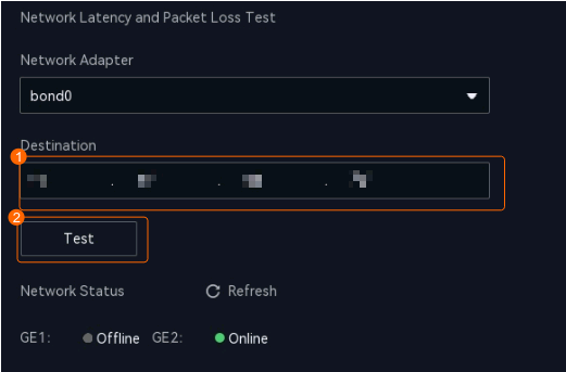
How Do I Check Whether the HWT-IVS1800 Is Properly Connected to the Target Network Environment?
Context
If the HWT-IVS1800 needs to exchange network data with other devices, ensure that the HWT-IVS1800 is properly connected to the network of the target device. You can enter the network IP address of the target device in the HWT-IVS1800 to check whether the connection to the target network environment is normal.
Network Connectivity Test (on the LDU)
- Log in to the LDU as the admin user. (
 Logging In to the LDU)
 - Choose System Management > System Settings > Network.
- Verify network connectivity, as shown in Figure 6-132.
Table 6-41 describes the key parameters.
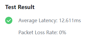
- View test results, as shown in Figure 6-133.

Network Connectivity Test (on the OMU Portal)
- Log in to the OMU portal as the admin user. ( Logging In to the OMU portal)
- Choose .
- Verify network connectivity, as shown in Figure 6-134.
Table 6-42 describes the key parameters.
- View test results, as shown in Figure 6-135.

Batch Network Connectivity Test (on the OMU Portal)
- Log in to the OMU portal as the admin user. (
 Logging In to the OMU portal)
 - Choose .
- Verify network connectivity, as shown in Figure 6-136.
Table 6-43 Parameter description
Parameter
Description
Search text box
IP address of the target device to be tested.
Duration
Ping duration. The default value is 86400 (By Seconds), and the maximum duration is 30 days. The unit of the value can be:
- By Seconds
- By Minute
- By the hour
- By day
Packet size(byte)
Maximum packet size. The default value is 1500 bytes, and the maximum value is 3000 bytes.
- View test results, as shown in Figure 6-137.
- (Optional) Click Download in the Operation column to view the logs of packet loss test, as shown in Figure 6-138.


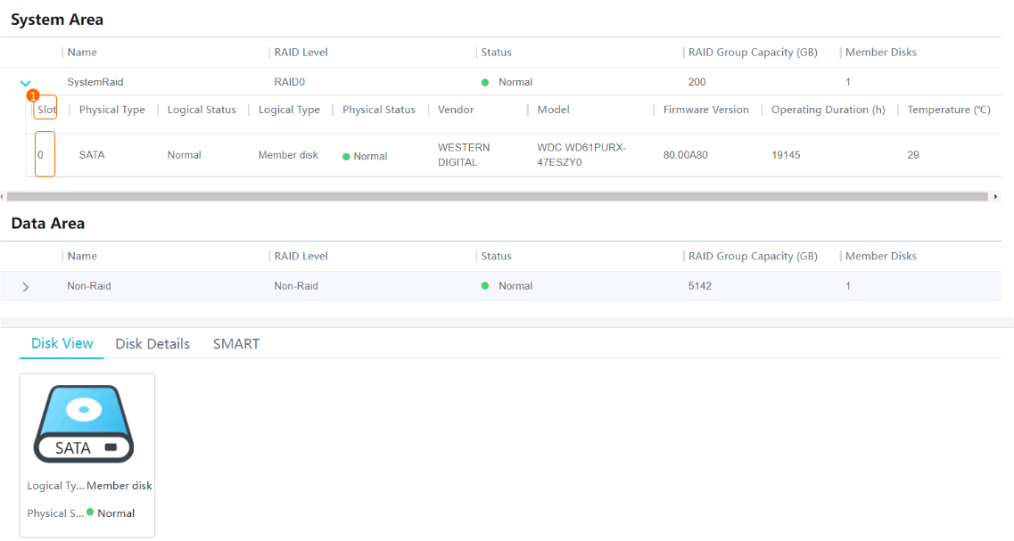
How Do I Distinguish Disk Partitions?
Context
- Normal disks inserted into the device can be classified into:
- Idle disk: The disk is not initialized, and data will not be stored on it.
- Member disk: The disk has been initialized, and data can be stored on it.
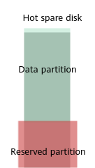
- Hot spare disk: In RAID 5 recommended mode, one disk is used as the hot spare disk. The hot spare disk does not store data. When a disk in the RAID group fails, the hot spare disk will replace the failed one and function as a member disk of the RAID group.
- The disk space of a member disk can be divided into the partitions shown in the following figure.Figure 6-139 Disk partitions
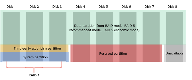
- Data partition
- Space for storing information such as recordings and images.
- This partition is user-defined.
Based on the disk quantity and reliability requirements, non-RAID mode, RAID 5 recommended mode, and RAID 5 economical mode are supported.
- Third-party algorithm partition
- Space for installing third-party algorithms.
- The partition size is manually set to X (cannot be changed after being set) when the disks are initialized for the first time.
- System partition
- Space for storing system data such as Data Safe data.
- The fixed size of this partition is 180 GB.
- If there is only one disk, the system partition is in RAID 0 mode.
- If there are two disks, the system partition is in RAID 1 mode.
- If there are more than two disks, the system partition is in RAID 1 mode, and another disk is used as the hot spare disk.
- Reserved partition
- Undefined partition, which can be used to store third-party algorithm files.
For details about how to view the space path of the reserved partition, see Related Operations.
- Undefined partition, which can be used to store third-party algorithm files.
- Unavailable partition
- Partition except for the data partition, system partition, and reserved partition.
- Data partition
- The following figure shows how to partition the space of the hot spare disk.Figure 6-140 Partitioning the space of the hot spare disk
Procedure
You can view the disks where a partition resides on the OMU portal.
- Log in to the OMU portal as the admin user. ( Logging In to the OMU portal)
- Choose Storage > Disks.
- Check the disks where the system partition resides, as shown in Figure 6-141.
Related Operations
- View the space path of a reserved partition.
- Log in to the operating system as the ivsoper user. ( How Do I Log In to the Operating System Through a Network Port?)
- View disk information.
lsblk
The following information is displayed:
- If TYPE is set to raid1, the disk is a system disk. Third-party algorithm installation packages can be stored in /opt/third_algorithm.
NAME         MAJ:MIN RM   SIZE RO TYPE   MOUNTPOINT
loop0          7:0    0   128M  0 loop  /SmartFS0
sda            8:0    0   3.6T  0 disk
├─sda1         8:1    0   3.5T  0 part  /opt/SmartData_D/G0_3
└─sda2         8:2    0 186.3G  0 part
sdb            8:16   0   3.6T  0 disk
├─sdb1         8:17   0   3.5T  0 part  /opt/SmartData_D/G0_4
└─sdb2         8:18   0 186.3G  0 part
sdc            8:32   0   5.5T  0 disk
├─sdc1         8:33   0   5.3T  0 part  /opt/SmartData_D/G0_5
└─sdc2         8:34   0 186.3G  0 part
sdd            8:48   0   7.3T  0 disk
├─sdd1         8:49   0   7.1T  0 part  /opt/SmartData_D/G0_6
└─sdd2         8:50   0 186.3G  0 part
  └─md0        9:0    0 186.1G  0 raid1
    ├─md0p1  259:1    0 131.3G  0 part  /opt
    ├─md0p2  259:2    0  18.6G  0 part  /opt/third_algorithm
    ├─md0p3  259:3    0   5.6G  0 part  /var/lib/docker
    └─md0p4  259:4    0  27.8G  0 part  /opt/third_algorithm_D
sde            8:64   0   3.6T  0 disk
├─sde1         8:65   0   3.5T  0 part  /opt/SmartData_D/G0_2
└─sde2         8:66   0 186.3G  0 part
sdf            8:80   0   3.6T  0 disk
├─sdf1         8:81   0   3.5T  0 part  /opt/SmartData_D/G0_0
└─sdf2         8:82   0 186.3G  0 part
  └─md0        9:0    0 186.1G  0 raid1
    ├─md0p1  259:1    0 131.3G  0 part  /opt
    ├─md0p2  259:2    0  18.6G  0 part  /opt/third_algorithm
    ├─md0p3  259:3    0   5.6G  0 part  /var/lib/docker
    └─md0p4  259:4    0  27.8G  0 part  /opt/third_algorithm_D
sdg            8:96   0   3.6T  0 disk
├─sdg1         8:97   0   3.5T  0 part  /opt/SmartData_D/G0_1
└─sdg2         8:98   0 186.3G  0 part
  └─md0        9:0    0 186.1G  0 raid1
    ├─md0p1  259:1    0 131.3G  0 part  /opt
    ├─md0p2  259:2    0  18.6G  0 part  /opt/third_algorithm
    ├─md0p3  259:3    0   5.6G  0 part  /var/lib/docker
    └─md0p4  259:4    0  27.8G  0 part  /opt/third_algorithm_D
mtdblock0     31:0    0     1M  0 disk
mtdblock1     31:1    0     1M  0 disk
mtdblock2     31:2    0     1M  0 disk
mtdblock3     31:3    0   512K  0 disk
mtdblock4     31:4    0  12.5M  0 disk
mmcblk0      179:0    0  29.1G  0 disk
├─mmcblk0p1  179:1    0   511M  0 part
├─mmcblk0p2  179:2    0     2G  0 part
├─mmcblk0p3  179:3    0     2G  0 part  /
├─mmcblk0p4  179:4    0     1G  0 part  /home/data
├─mmcblk0p5  179:5    0     1G  0 part  /home/log
├─mmcblk0p6  179:6    0   6.5G  0 part  /home
├─mmcblk0p7  179:7    0    10G  0 part  /DB_DATA
└─mmcblk0p8  259:0    0     6G  0 part  /StaticFeature
mmcblk0boot0 179:8    0     4M  1 disk
mmcblk0boot1 179:16   0     4M  1 disk
- Log in to the operating system as the ivsoper user. (
Slow Disk Fault Detection
Scenario Description
If the read/write speed decreases or the number of read/write errors increases due to disk aging, the disk becomes a slow disk. You can receive slow disk alarms on the iClient S100 or view slow disk alarms on the storage management page of the OMU portal.
The HWT-IVS1800 automatically detects and isolates slow disks. You need to replace slow disks as soon as possible to ensure stable system running.
Procedure
Log in to the OMU portal, choose , and check the disk status. If a disk is displayed as a slow disk, you only need to handle this disk.
- Log in to the OMU portal as the admin user. ( Logging In to the OMU portal)
- Choose , find the disk whose Physical Status is Slow disk, and confirm the disk slot number, as shown in Figure 6-142.
- Locate the disk in the corresponding slot on the HWT-IVS1800, replace the disk by referring to steps 2 through 6, and wait for 10 minutes.
- On the OMU portal, choose and check whether there are any slow disks. If so, contact technical support. If not, the fault is rectified.

Procedure for Handling Other Exceptions
If you receive fault alarms of multiple slow disks from the iClient S100 at the same time, or find multiple slow disks on the Storage page of the OMU portal, the possible cause is that a specific fault occurs on a disk, which affects the read and write operations of other disks. To rectify the fault, you can perform the following steps to replace disks one by one.
- Log in to the OMU portal as the admin user. ( Logging In to the OMU portal)
- Choose and select only Disk faults.
- Click Check to start the inspection, as shown in Figure 6-143. Wait until the inspection is complete, and the completed time is updated.
- Click View Last Result to view the check result.
- On the Check Result page, click By Result to view the result of checking disk faults, as shown in Figure 6-144.
- If the result contains "Slow disk slot id x", remove the disk in slot x from the HWT-IVS1800 and restart the system. Wait for about 5 minutes after the restart and check whether slow disks still exist on the storage page of the OMU portal.
- If so, repeat Step 1 through Step 6. If slow disks still exist after two rounds of operations, contact technical support.
- If not, replace the disk removed in the last step with a new one by referring to steps 2 through 6. If no slow disk exists after multiple rounds of the preceding operations, insert the removed disks back to the slots.


Cloud Service Interconnection Capability Set
Type |
Function |
|---|---|
Device management |
Supports IVS1800 registration with the cloud service, channel and status report, and time synchronization. |
Live video viewing and voice intercom |
Supports live video viewing, PTZ control, channel-associated voice, voice intercom, and OSD setting. |
Recording playback |
Supports recording query and playback. |
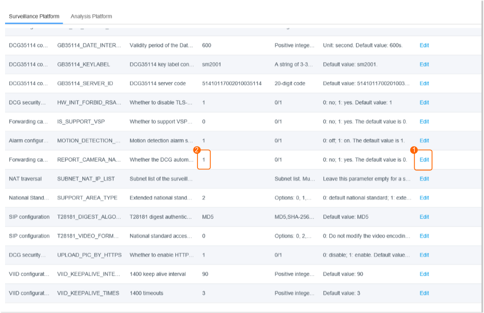
How Do I Configure the Platform to Display the Video Channel Name as a Camera Name After the HWT-IVS1800 Is Connected to the IVS3800 or IVS2800 Through GB/T 28181?
Symptom
After the HWT-IVS1800 is connected to the IVS3800 or IVS2800 through GB/T 28181, the video channel name of the HWT-IVS1800 is displayed as HWT-IVS1800Access name01***, as shown in Figure 6-145.
Scenario Description
To display the video channel name as a camera name, you must perform steps in Procedure to set related parameters on the CSP OM portal before connecting the HWT-IVS1800 to the IVS3800 or IVS2800. Otherwise, you need to reconnect the HWT-IVS1800 to the IVS3800 or IVS2800.
Procedure
- Log in to the CSP OM portal as the admin user.
- Choose Application Configuration > Configuration Management > Configuration > Unified Configuration > Video/Image Management Platform.
- Set Service to VCNDCGService.
- Set Whether the DCG automatically reports camera names, as shown in Figure 6-146.
How Can I Enable the SSH Function?
Context
- The SSH function is disabled by default.
- For security purposes, you are advised to disable the SSH function in a timely manner after using it.
Procedure
- Method 1: Press and hold the reset button for 1 second.
- Method 2: Enable the SSH function when you log in to the LDU for the first time. For details, see 9.
- Method 3: Log in to the OMU portal, choose System > Basic Settings, and enable the SSH function.
The SSH function can be disabled only on the OMU portal.
- Method 4: Enable the SSH function through a serial port.
What Can I Do If Live and Recorded Video Cannot Be Properly Played After Data Is Restored in the Subrack Replacement Scenario?
Symptom
After data is restored using the Data Safe in the subrack replacement scenario, live and recorded video cannot be properly played.
Possible Causes
The version of the device before subrack replacement (referred to as the old device) is different from that of the device after subrack replacement (referred to as the new device). As a result, data cannot be properly restored.
Procedure
- Reinstall the software of the new device to the device version backed up in the Data Safe if these two versions are different. For details about how to check the device version backed up in the Data Safe, see How Do I Check the Version of the Device Whose Data Is Backed up in the Data Safe?. For details about how to check the software version of the new device, see How Do I Check the Device Version?.
- Restore data by referring to Restoring Data Using the Data Safe.
- After the data is restored, upgrade the device software to the latest version.
What Can I Do When Unexpected Power-off Occurs?
Unexpected Power-off During System Reinstallation
Scenario
During system reinstallation, the reinstallation is interrupted due to unexpected power-off.
Impact on Services
- The reinstallation fails due to interruption.
- Services are affected after the device is powered on again. For example, the OMU portal cannot be logged in.
Procedure
- Perform the reinstallation again after the device is powered off.
Unexpected Power-off During Factory Setting Restoration
Scenario
The factory setting restoration is interrupted due to unexpected power-off.
Impact on Services
- Services may be affected after the device is powered on.Whether the factory setting restoration can be resumed after the device is powered on again depends on the phase in which unexpected power-off occurs.
- If the factory setting restoration can be resumed:
- After the factory setting restoration is complete, the device IP address is restored to 192.168.3.111 (default IP address). In this case, the device is restored to factory settings successfully and all service configurations are lost.
- After the factory setting restoration is complete, the device IP address remains unchanged. In this case, the device fails to be restored to factory settings and no services are affected.
- If the factory setting restoration cannot be resumed, services are affected. For example, the OMU portal cannot be logged in. In this case, you need to perform factory setting restoration again.
- If the factory setting restoration can be resumed:
Procedure
- Power on the device, wait for a period of time, and check whether the device can be restored to factory settings.
- It takes about 18 minutes for an HWT-IVS1800-E or HWT-IVS1800-D device.
- Check whether you can log in to the OMU portal of the device.
- If the login is successful, check whether the default network settings are used.By default, the IP address of the device is 192.168.3.111 and the network mode is single-address mode.
- If the default network settings are used, the factory setting restoration is successful.
- If the default network settings are not used, perform factory setting restoration again.
- If the login fails, perform factory setting restoration again.
- If the login is successful, check whether the default network settings are used.
Unexpected Power-off During Data Restoration
Scenario
During data restoration, the restoration is interrupted due to unexpected power-off.
Impact on Services
- The data restoration fails due to interruption.
- Services are affected after the device is powered on again. For example, the OMU portal cannot be logged in.
Data Clearance Rules
Data Source |
Clearance Rule |
|---|---|
Alarm-triggered snapshots |
Alarm-triggered snapshots are cleared when the snapshot storage period ends or the number of snapshots reaches 20,000. |
Automatic snapshots |
Snapshots stored in alarm records will be cleared when the snapshot storage period ends or cleared with alarm records. |
Dynamic lists |
|
Alarm records |
|
Recording segment indexes |
A single camera supports a maximum of 20,000 recording segment indexes. In normal cases, 1 GB recording data or one alarm-triggered recording will generate one recording segment index.
|
Recording record |
When you query recordings of a single video channel on the HWT-IVS1800, a maximum of 1000 records can be returned, including alarm-triggered recordings and scheduled recordings. Recording records can be queried in the following scenarios:
|
How Do I Clear Buzzer Alarms?
Buzzer Alarm |
Fault Type |
Alarm Clearance Method |
|---|---|---|
Two short beeps followed by two long beeps (repeated for 300s) |
Disk mounting is abnormal. |
If the buzzer generates two short beeps and two long beeps for two consecutive times, check the disk mounting status. |
Two short beeps (repeated for 300s) |
A slow disk alarm occurs. |
If the buzzer generates two short beeps for two consecutive times, rectify the fault by referring to Slow Disk Fault Detection. |
Two short beeps followed by one long beep (repeated for 30s) |
A system time error occurs. |
If the buzzer generates two short beeps and one long beep for two consecutive times, check the system time on the OMU portal. |
One long beep followed by two short beeps (repeated for 30s) |
The real-time clock (RTC) battery voltage is low. |
If the buzzer generates one long beep and two short beeps for two consecutive times, check the battery health status. |
One long beep followed by one short beep, lasting 30s (repeated for 60s) |
Data restoration using the Data Safe fails. |
If the buzzer generates one long beep and one short beep for 30s, restore the factory settings and check the device startup status by referring to How Do I Restore a Device to Factory Settings?. |
Long beep |
The eMMC service life is about to end. |
If the buzzer generates a long beep, you are advised to replace the subrack. |
How Do I Enable the Debugging Mode?
- Log in to the operating system as the root user. ( How Do I Log In to the Operating System Through a Network Port?)
- Go to /home/ivs_common.
cd /home/ivs_common
- Delete the nodebug file to enable the debugging mode.
rm nodebug
- Disable the debugging mode for security purposes.
touch nodebug
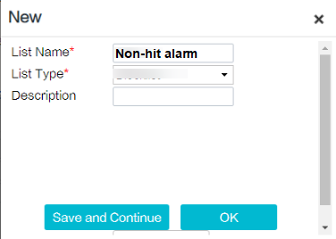
How Do I Set Target Alarms When a Camera Uses the Optimal Capture Mode?
Prerequisites
- The target detection function has been enabled and the capture mode has been set to Optimal for the camera.
- The Mode parameter is not set to Target capture under Intelligent Application > Camera Intelligence for the HWT-IVS1800.
Procedure
- Create an empty list by referring to Feature Configuration, and name it Non-hit alarm, as shown in Figure 6-147 and Figure 6-148.
- Log in to the OMU portal as the admin user. ( Logging In to the OMU portal)
- View the MCS module under System > Advanced Configuration, set AlarmFaceMSG to 1, and save the setting.
- Check target recognition alarms on the iClient S100 or HWT-IVS1800 LDU by referring to Procedure (on the iClient S100) and Procedure (on the LDU). For details, see Figure 6-149 and Figure 6-150.


What Can I Do If the Number of Snapshot Alarms Delivered by the IVS1800 Is Inconsistent with That in the Camera Web System?
Symptom
In the same period, the number of snapshot alarms delivered by the IVS1800 to the LDU or iClient S100 is inconsistent with that in the camera web system.
Possible Causes
A camera is connected to multiple IVS1800s, and multiple IVS1800s deliver alarm-triggered snapshot requests at the same time. As a result, some alarm-triggered snapshots fail to be delivered.
Solution
Connect one camera to only one IVS1800.
How Do I Handle the Network Communication Failure Caused by the Conflict Between the HWT-IVS1800 and the Docker0 Network Adapter?
Context
By default, the docker0 network adapter uses an IP address in the 172.17.0.0/16 network segment. If the network adapter (eth0 or eth1) resides in the same network segment as docker0, the network may be disconnected.
Procedure
- Disable the docker0 network adapter.
ifdown docker0
- Change the default IP address of the docker0 network adapter.
- Log in to the operating system as the root user. ( How Do I Log In to the Operating System Through a Network Port?)
- Check the initial IP address of the docker.
route -n
Kernel IP routing table
Destination     Gateway         Genmask         Flags Metric Ref    Use Iface
....
172.17.0.0     0.0.0.0         255.255.0.0     U     0      0        0 docker0
- Start the docker.
service docker start
- Check the running status of the docker container.
docker ps -a
- If the container is empty, no third-party algorithm exists in the current container.
CONTAINER ID IMAGE COMMAND CREATED STATUS PORTS NAMES
- If the container status is Up, run the docker stop Container ID command, for example, docker stop bea7af01d449, to stop a specific container.
CONTAINER ID        IMAGE               COMMAND                  CREATED             STATUS              PORTS              NAMES
bea7af01d449        helmet:helmet       "/bin/bash -c /home/…"   10 hours ago       Up 10 seconds                           helmet
If the container cannot be stopped, stop the analysis task that the third-party algorithm of the container is running, and then stop the container again.
- If the container status is Exited, the container is stopped.
CONTAINER ID        IMAGE               COMMAND                  CREATED             STATUS                    PORTS               NAMES
bea7af01d449        helmet:helmet       "/bin/bash -c /home/…"   10 hours ago        Exited (0) 10 hours ago                       helmet
- If the container is empty, no third-party algorithm exists in the current container.
- Modify the daemon.json file.
vi /etc/docker/daemon.json
- If the daemon.json file does not contain any content, copy the following content to it:
{ "bip":"192.168.0.1/16" }In the preceding information, 192.168 indicates the new network segment used by docker0. Change it based on the site requirements.
- If the daemon.json file already contains information, add the following content in bold to the file and separate the content with commas (,).
{ "insecure-registries":["XXX.XXX.XXX.XXX:5300","swr.cn-north-7.mycloud.com"],"bip":"192.168.0.1/16"}In the preceding information, 192.168 indicates the new network segment used by docker0. Change it based on the site requirements.
- If the daemon.json file does not contain any content, copy the following content to it:
- Load the configuration file again.
systemctl daemon-reload
- Restart the docker.
systemctl restart docker
- Log in to the operating system as the root user. (
What Can I Do If a Camera Connected to the HWT-IVS1800 Is in Offline State and Fails to Automatically Go Online After It Is Restored to Factory Settings?
Symptom
After a camera connected to the HWT-IVS1800 is restored to factory settings, the camera is in offline state on the iClient S100 and fails to automatically go online.
Possible Causes
After the camera is restored to factory settings, it is in unactivated state. The HWT-IVS1800 identifies that the camera is in offline state and triggers activation and re-login of the camera.
If you activate a camera in the camera web system before the HWT-IVS1800 triggers activation and login of the camera, the HWT-IVS1800 cannot identify the camera status. As a result, the camera is in offline state on the iClient S100 and fails to automatically go online.
Solution
You can solve this problem in any of the following ways:
- Log in to the offline camera on the iClient S100.
- On the iClient S100 home page, choose .
- Select the desired HWT-IVS1800 device. In the camera list, right-click the offline camera that failed to automatically go online, and choose Login from the shortcut menu.
- In the dialog box that is displayed, enter the user name and password, and click OK, as shown in Figure 6-151.
The entered password must be the same as the password for logging in to the camera web system.

- Add the camera again through HWT-IVS1800. For details, see Connecting Common Cameras.
- Restart the DCG. For details, see Restarting Service Modules. After the restart, you can check whether the camera is online on the iClient S100. If the camera is still offline, rectify the fault by referring to the preceding two solutions.
What Can I Do If the Alarm-triggered Recording Is Delayed or Partially Lost?
Symptom
After video recording linkage is configured and multiple recording channels are selected, the alarm-triggered recording is delayed or partially lost. The following figure shows an example of this symptom on the iClient S100.

Root Cause
During the configuration of video recording linkage and multiple recording channels, the request message for the HWT-IVS1800 to pull streams is blocked by other messages, causing a delay or failure of response to the stream pulling request. As a result, the recording is delayed or even lost.
Solution
Enable Scheduled Recording. The time segment of the scheduled recording must contain the time segment of the alarm-triggered recording.
- For details about how to configure scheduled recording on the iClient S100, see Configuring Scheduled Server Recording.
- For details about how to configure scheduled recording on the LDU, see Setting Recording Parameters.
What Can I Do If the System Displays a Message Indicating That the Upgrade Fails Due to Invalid Operation When I Perform HWT-IVS1800 Upgrade on the iClient S100?
Symptom
After the HWT-IVS1800 upgrade package is uploaded to the iClient S100, a power outage occurs during the upgrade. After the device is powered on and the upgrade is performed again, a message is displayed on the iClient S100, indicating that the upgrade fails due to invalid operation.
Root Cause
During the upgrade, the iClient S100 or HWT-IVS1800 is powered off or disconnected from the network, resulting in upgrade file transmission interruption. When the upgrade is performed again, the HWT-IVS1800 determines that the previous file transmission is not complete and does not perform a new upgrade task.
Solution
- Perform the local upgrade through the OMU portal. For details, see the HWT-IVS1800 Upgrade Guide.
You can log in to https://www.holowits.com/documentation, search for the desired device model, and obtain the upgrade guide of the desired version.
- Upgrade the iClient S100 to V3.3.0 or later, and then upgrade the HWT-IVS1800 again. For details about how to download the iClient S100 installation package, visit https://www.holowits.com/soft-download.
What Should I Do If the Upgrade Fails Due to Insufficient Directory Space in Diskless Upgrade Scenarios on the LDU or OMU Portal?
Symptom
When the diskless upgrade is performed after the HWT-IVS1800 upgrade package is uploaded on the LDU or OMU portal, the upgrade fails, and one of the following causes is displayed:
- In the diskless upgrade scenario, the upgrade directory space is insufficient
- In the diskless upgrade scenario, the backup directory space is insufficient
- In the diskless upgrade scenario, the directory for uploading packages space is insufficient
Root Cause
The directory space is used up and the space required for the upgrade is insufficient.
Solution
- Log in to the operating system as the root user. ( How Do I Log In to the Operating System Through a Network Port?)
- Release the space based on the failure cause displayed on the page.
- If In the diskless upgrade scenario, the upgrade directory space is insufficient is displayed, run the following command:
find /StaticFeature -maxdepth 1 ! -name 'StaticFeature' ! -name 'static' -exec rm -r {} +
- If In the diskless upgrade scenario, the backup directory space is insufficient is displayed, run the following command:
rm -rf /upgrade/*
- If In the diskless upgrade scenario, the directory for uploading packages space is insufficient is displayed, run the following command:
find /DB_DATA -maxdepth 1 ! -name 'data' ! -name 'DB_DATA' -exec rm -r {} +
- If In the diskless upgrade scenario, the upgrade directory space is insufficient is displayed, run the following command:
What Do I Do If Services of Some Modules Cannot Be Started After the Subrack of the HWT-IVS1800 Is Replaced and Data Is Restored Using the Data Safe?
Symptom
After the subrack of the HWT-IVS1800 is replaced, data is restored using the Data Safe. However, services of multiple modules cannot be started.
Root Cause
As the eMMC service life has ended, the files backed up using the Data Safe are abnormal. After the subrack is replaced and data is restored, the service module files are abnormal and services cannot be started.
Supported Devices
IVS1800-E series devices of 11.1 or later versions and V7000-08A-LLM series devices of 12.0 or later versions
Solution
- For all functions except check_business, place the Full.zip installation package of the same version to the /tmp directory of the device.
- Enter command-line arguments.
In 12.0.0.SPC60 and later versions, the built-in emmc_recover script is available. In other versions, you need to upload the script to the environment.
Enter command-line arguments to run the bash /home/ivstool/bin/emmc_recover.sh script.
Select the following command-line arguments as required:
- check: compares the latest backup set of the files in the environment with the installation package in /tmp and lists the differences between the files in the installation package and the files in the environment (the file does not exist or the MD5 values are different).
- recover: replaces the files in the environment with the files in the installation package.
- check_and_recover: compares and then replaces files.
- check_business: checks whether all services are started, with no need to upload the installation package to the tmp directory.
- check_with_cann: similar to check, with an additional check on the CANN package.
- recover_with_cann: similar to recover, with an additional replacement of the CANN package.
- check_and_recover_with_cann: similar to recover, with an additional check and replacement of the CANN package.
- Stub_Verify: stubbing script dedicated for testing and used to delete recover.
- Stub_Verify_with_cann: similar to Stub_Verify, with an additional deletion of the CANN package.
Verification
The script execution result is recorded in /tmp/result.txt.
How Do I Check the Available Space of the /home Directory?
Context
Before upgrading large model algorithms, you need to check the available space of the /home directory. The available space must be 600 MB at least.
Procedure
- Log in to the operating system as the root user. ( How Do I Log In to the Operating System Through a Network Port?)
- Check the available space of the /home directory. Ensure that the available space is 600 MB at least, as shown in Figure 6-153.
df -h
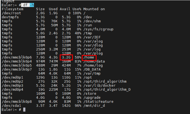
What Do I Do If the VA Algorithm Plug-in Fails to Be Installed Due to Insufficient Space of the /home Directory?
Context
Before large model algorithms are installed, the space of the /home directory is not checked. The algorithm plug-in fails to be installed due to insufficient space of the /home directory.
Procedure
- Choose on the OMU portal.
- Log in to the operating system as the root user. ( How Do I Log In to the Operating System Through a Network Port?)
- Check the available space of /home and the space usage, as shown in Figure 6-154.
df -h
- Delete unnecessary directories and files.
du -sh *

- Delete the corresponding algorithm directory.
cd /home/lib/ivs_va/plugin


How Do I Restore a Saved Recording File That Is Lost in RAID Mode?
Symptom
A recording file is lost in RAID mode.
Possible Causes
- A recording file is lost due to bad sectors on disks.
- After a device is recovered from frequent power-offs, a recording file is lost because some video clips in the file fail to be flushed to disks.
Prerequisites
You have performed the following operations to obtain the IDs of the damaged blocks in the database.
Obtaining the IDs of the Damaged Blocks in the Database
- Log in to the database as the scuadmin user.
- Run the following SQL statement:
select * from device_cameraCode
cameraCode indicates the channel ID. If there is a large amount of data, you can filter the data by time.

Solution
- Log in to the operating system as the root user. ( How Do I Log In to the Operating System Through a Network Port?)
- Go to the tool path.
/home/ivs_mu/bin/video_tool

- Find the paths of the block files.

- Run the following commands:
export LD_LIBRARY_PATH=/home/lib
video_recover Recover fold_num block_path audioFormatNum
- Example command: /home/ivs_mu/bin/video_tool/video_recover Recover 0000 /diskmount/0000/000001 1
- Fold_num is set to 0000.
- Block_path is set to /diskmount/0000/000001.
- audioFormat is set to 1. (If the audio format is G.711A, enter 1. Otherwise, you can enter 1, 2, 3, and 4 to find the correct value.) The mapping between audioFormat values and audio formats is as follows:
- G.711A = 1
- G.711U = 2
- G.726 = 3
- AAC = 4
- Example command: /home/ivs_mu/bin/video_tool/video_recover Recover 0000 /diskmount/0000/000001 1
- After the execution is complete, a restored MP4 recording file is generated in the current path.
How Do I Improve the Detection Rate of an Inspection Large Model Algorithm?
Symptom
After an inspection large model task is created, the task fails to be triggered. How do I improve the detection rate of the algorithm.
Solution
Adjust algorithm parameters or alert parameters to improve the detection rate of the algorithm.
- Adjust algorithm parameters.

- Increase the algorithm sensitivity to improve the object detection probability, thereby improving the detection rate of the algorithm.
- Decrease the alarm interval to increase the alarm frequency for the same object.
- Adjust alert parameters.

- Decrease the value of Minimum detection target to improve the detection rate of small objects.
- Increase the value of Maximum detection target to improve the detection rate of large objects.
How Do I Reduce the False Positive Rate of an Inspection Large Model Algorithm?
Symptom
After an inspection large model task is created, too many false positives are reported. How do I reduce the false positive rate of the algorithm?
Solution
Adjust algorithm parameters, adjust alert parameters, or use a false positive library to reduce the false positive rate of the algorithm.
- Adjust algorithm parameters.
- Decrease the algorithm sensitivity to improve the algorithm accuracy, thereby reducing the false positive rate.
- Increase the alarm interval to reduce the alarm frequency for the same object, thereby reducing the number of alarms.
- Adjust alert parameters.
- Increase the value of Minimum detection target to reduce the false positive rate of small objects.
- Decrease the value of Maximum detection target to reduce the false positive rate of large objects.
- Use a false positive library.

- In the real-time or historical alarm list, click Wrong alarm to add the alarm image to the false positive library to reduce the number of false positives for similar objects.
How Do I Determine Whether the Current Object Size Meets the Specifications of an Inspection Large Model Algorithm?
Solution
Check the object size compliance when you deploy alert for an inspection task or when you view alarms after the alert deployment.
- When you deploy alert for an inspection task:

- When you adjust the values of Minimum detection target and Maximum detection target, the sizes of the green and purple boxes in the video image change accordingly. You can check whether the values met specifications based on the size relationship between the object and the boxes in the video image.
- When you view alarms after the alert deployment:

- Click Download Alarm Picture to download the alarm image to the computer. Open Microsoft Paint, import the alarm image to Microsoft Paint, and adjust the canvas size to 1920 × 1080. Then, box-select the object and check the object size based on the sizes in the lower left corner.
What Do I Do If No Alarm Is Reported for the Cloud Service?
Possible Causes
Connecting the cloud service to the HWT-IVS1800 occupies client connections. When the number of client connections exceeds the upper limit, no alarm is reported for the cloud service.
Solution
Disconnect some clients and check whether alarms can be reported properly.
- Log in to the OMU portal as the admin user. ( Logging In to the OMU portal)
- Choose and check the number of login clients on the computer.
- Disconnect some clients on the computer until alarms can be reported properly.
- How Do I Manually Partition a Disk?
- How Do I Restore a Device to Factory Settings?
- How Do I Reinstall the IVS Service System ?
- How Do I Enter the Private Key Password During System Reinstallation?
- How Do I Log In to the Operating System Through a Serial Port?
- How Do I Log In to the Operating System Through a Network Port?
- How Do I Enable and Disable Local Login to the Database?
- How Do I Connect Cables and Configure Alarm Input and Output Ports?
- What Do I Do If No Signal Is Displayed on a Monitor When It Is Connected to the Device Using the HDMI Port?
- How Do I View the Serial Number of the HWT-IVS1800?
- How Do I View the Specifications of the HWT-IVS1800?
- How Do I View the Verification Code of the HWT-IVS1800?
- What Can I Do If the Device Does Not Respond After Power-on?
- How Do I Power On and Power Off a Device Correctly?
- How Do I Configure Port Aggregation?
- How Do I Check Whether the HWT-IVS1800 Is Properly Connected to the Target Network Environment?
- How Do I Distinguish Disk Partitions?
- Slow Disk Fault Detection
- Cloud Service Interconnection Capability Set
- How Do I Configure the Platform to Display the Video Channel Name as a Camera Name After the HWT-IVS1800 Is Connected to the IVS3800 or IVS2800 Through GB/T 28181?
- How Can I Enable the SSH Function?
- What Can I Do If Live and Recorded Video Cannot Be Properly Played After Data Is Restored in the Subrack Replacement Scenario?
- What Can I Do When Unexpected Power-off Occurs?
- Data Clearance Rules
- How Do I Clear Buzzer Alarms?
- How Do I Enable the Debugging Mode?
- How Do I Set Target Alarms When a Camera Uses the Optimal Capture Mode?
- What Can I Do If the Number of Snapshot Alarms Delivered by the IVS1800 Is Inconsistent with That in the Camera Web System?
- How Do I Handle the Network Communication Failure Caused by the Conflict Between the HWT-IVS1800 and the Docker0 Network Adapter?
- What Can I Do If a Camera Connected to the HWT-IVS1800 Is in Offline State and Fails to Automatically Go Online After It Is Restored to Factory Settings?
- What Can I Do If the Alarm-triggered Recording Is Delayed or Partially Lost?
- What Can I Do If the System Displays a Message Indicating That the Upgrade Fails Due to Invalid Operation When I Perform HWT-IVS1800 Upgrade on the iClient S100?
- What Should I Do If the Upgrade Fails Due to Insufficient Directory Space in Diskless Upgrade Scenarios on the LDU or OMU Portal?
- What Do I Do If Services of Some Modules Cannot Be Started After the Subrack of the HWT-IVS1800 Is Replaced and Data Is Restored Using the Data Safe?
- How Do I Check the Available Space of the /home Directory?
- What Do I Do If the VA Algorithm Plug-in Fails to Be Installed Due to Insufficient Space of the /home Directory?
- How Do I Restore a Saved Recording File That Is Lost in RAID Mode?
- How Do I Improve the Detection Rate of an Inspection Large Model Algorithm?
- How Do I Reduce the False Positive Rate of an Inspection Large Model Algorithm?
- How Do I Determine Whether the Current Object Size Meets the Specifications of an Inspection Large Model Algorithm?
- What Do I Do If No Alarm Is Reported for the Cloud Service?